48 x8 with split network system – Momentum Sales & Marketing PRO CO MO8 User Manual
Page 13
13
Momentum mo8 Manual
Connection and Setup
Chapter 2
Connection and Setup
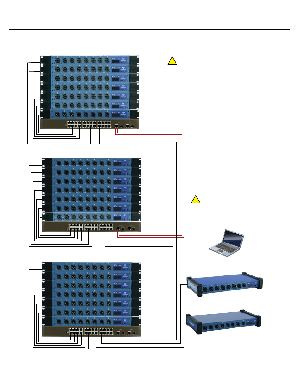
48 x8 With Split Network System
mi8 Input
Chn=001 Adr=001
mi8 Input
Chn=009 Adr=002
mi8 Input
Chn=017 Adr=003
mi8 Input
Chn=025 Adr=004
mi8 Input
Chn=033 Adr=005
mi8 Input
Chn=041 Adr=006
mo8 Output
Chn=049 Adr=009
STAGE
mo8 Output
Chn=001 Adr=010
mo8 Output
Chn=009 Adr=011
Chn=017 Adr=012
Chn=025 Adr=013
Chn=033 Adr=014
Chn=041 Adr=015
mi8 Input
Chn=049 Adr=007
mo8 Output
mo8 Output
mo8 Output
mo8 Output
FOH
CAT5E or CAT6
Optional Fiber
Managed
Ethernet Switch
Control PC
If running over 48 channels, you MUST
set the Ethernet port that is connected
to your control PC to multicast filtering.
Multicast MAC 01:15:AB:C6:00:00
(See Network Design White Papers)
!
!
mo8 Output
Chn=001
mo8 Output
Chn=009
Chn=017
Chn=025
Chn=033
Chn=041
mo8 Output
mo8 Output
mo8 Output
mo8 Output
Additional Split
Chn=049
mo8 Output
mi8 Input
Chn=057 Adr=008
mo8 Output
Chn=057 Adr=023
Adr=016
Adr=017
Adr=018
Adr=019
Adr=020
Adr=021
Adr=022
Note:
Up to 256 inputs channels, and unlimited
outputs or DSPs can be added anywhere on the
network using this method.
Note:
Running both Fiber and CAT6 copper or two
CAT6 copper connections can provide a
redundant link between FOH and the Stage .
Ethernet Switches must be configured using
Spanning Tree Protocol.
Managed
Ethernet Switch
Managed
Ethernet Switch
Chn 001 must be present on the
network at all times. This unit will sync
the network clock.
mo8 Outpu
Chn=057 A
mi8 Input
Chn 057 Ad