MITSUBISHI ELECTRIC SRK50Z J-S User Manual
Page 23
-
22
-
'10 • SR-T
-091D
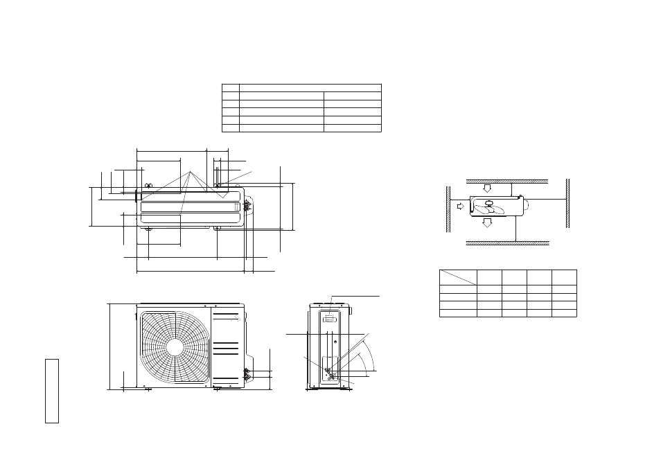
Models SRC50ZIX-S, 60ZIX-S
R
C
T
0
0
0
Z
0
0
4
Terminal block
L2
Intake
Outlet
Intake
L3
L1
L4
Service
space
( )
Minimum installation space
Notes
(
1) It must not be surrounded by walls on the four sides.
(
2) The unit must be fixed with anchor bolts. An anchor bolt must not
protrude more the 15mm.
(
3) Where the unit is subject to strong winds, lay it in such
a direction that the blower outlet faces perpendicularly
to the dominant wind direction.
(
4) Leave 1m or more space above the unit.
(
5) A wall in front of the blower outlet must not exceed the units height.
(
6) The model name label is attached on the lower right corner of the front panel.
A
C
D
B
E
φ
12.7(1/2")(Flare)
Content
C
Pipe/cable draw-out hole
D
E
Anchor bolt hole
Drain discharge hole
Symbol
B
A
Service valve connection(gas side)
M10 × 4places
φ
20 × 5places
Service valve connection(liquid side)
φ
6.35(1/4")(Flare)
Unit:mm
93
42.5
640
800
89
510
201
327.3
83.5
290
43.5
327.3
50.6
12
24.3
312.5
14.8
71.2
17.9
40°
40°
33.5
148.4
12.4
351.6
L2
L3
L4
L1
100
100
250
Open
I
I
I
Open
250
80
280
I
II
280
Open
80
75
Examples of
Dimensions
installation
IV
180
Open
80
Open
38.6
90.6
520.6
161
35.6