Bus_port, Keypad / port h, P_com1 and p_com2 – Motorola CML12S-DP256 User Manual
Page 17
C M L 1 2 S D P 2 5 6
0 7 / 1 7 / 0 2
17
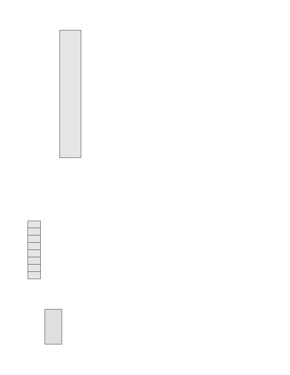
BUS_PORT
GND
1 2
D11/PA3
PA2/D10
3 4
D12/PA4
PA1/D9
5 6
D13/PA5
PA0/D8
7 8
D14/PA6
A0
9 10 D15/PA7
A1 11 12 A2
A10 13 14 A3
OE* 15 16 A4
A11 17 18 A5
A9 19 20 A6
A8 21 22 A7
A12 23 24 A13
WE*
25 26 A14
PE3/LSTRB* 27 28 A15
PE5/MODA 29 30 PE7/NOACC **
PE6/MODB 31 32 PE1/IRQ*
+5V 33 34 PE0/ XIRQ*
PE2/RW
35 36 RESERVED
PE4/ECLK 37 38 RESERVED
GND 39 40 RESET*
The BUS_PORT supports off-board memory devices
while the HCS12 is in expanded mode.
PA0/D8 - PA7/D15 High Byte Data Bus in Wide
Expanded Mode. Port A in Single Chip Mode.
A0 – A15 Latched Memory Addresses 0 to 15.
OE* Memory Output Enable signal, Active Low. Valid
with ECLK and R/W high.
WE* Memory Write Enable signal, Active Low. Valid
with ECLK high and R/W low.
RESET* HCS12 active low RESET signal.
KEYPAD / PORT H
The KEYPAD / PORT H connector provides interface for the HCS12 port H or applying a
keypad such as the Axiom Mfg. HC-KP. When applied as a KEYPAD connector, the interface
is for a passive 4 x 4 matrix (16 key) keypad device.
1
PH0
2
PH1
3
PH2
4
PH3
5
PH4
6
PH5
7
PH6
8
PH7
This interface is implemented as a software key scan. Pins PH0-3 are
used as column drivers which are active high outputs. Pins PH4-7 are
used for row input and will read high when their row is high.
See the file Key12Dx.ASM for an example program using this
connector.
P_COM1 and P_COM2
1 1
6
TXD0 2 6 7
RXD0 3 7 8
4 4 8 9
GND 5 9 X
The COM-1 port has a Female DB9 connector that interfaces to
the HCS12 internal SCI0 serial port via the U11 RS232
transceiver. It uses a simple 2 wire asynchronous serial
interface and is translated to RS232 signaling levels.
1,4,6 connected and 7,8 connected