Table 5-75 field descriptions – Maxtor 10K V User Manual
Page 112
5-54
Maxtor Atlas 10K V
5.12.12.1
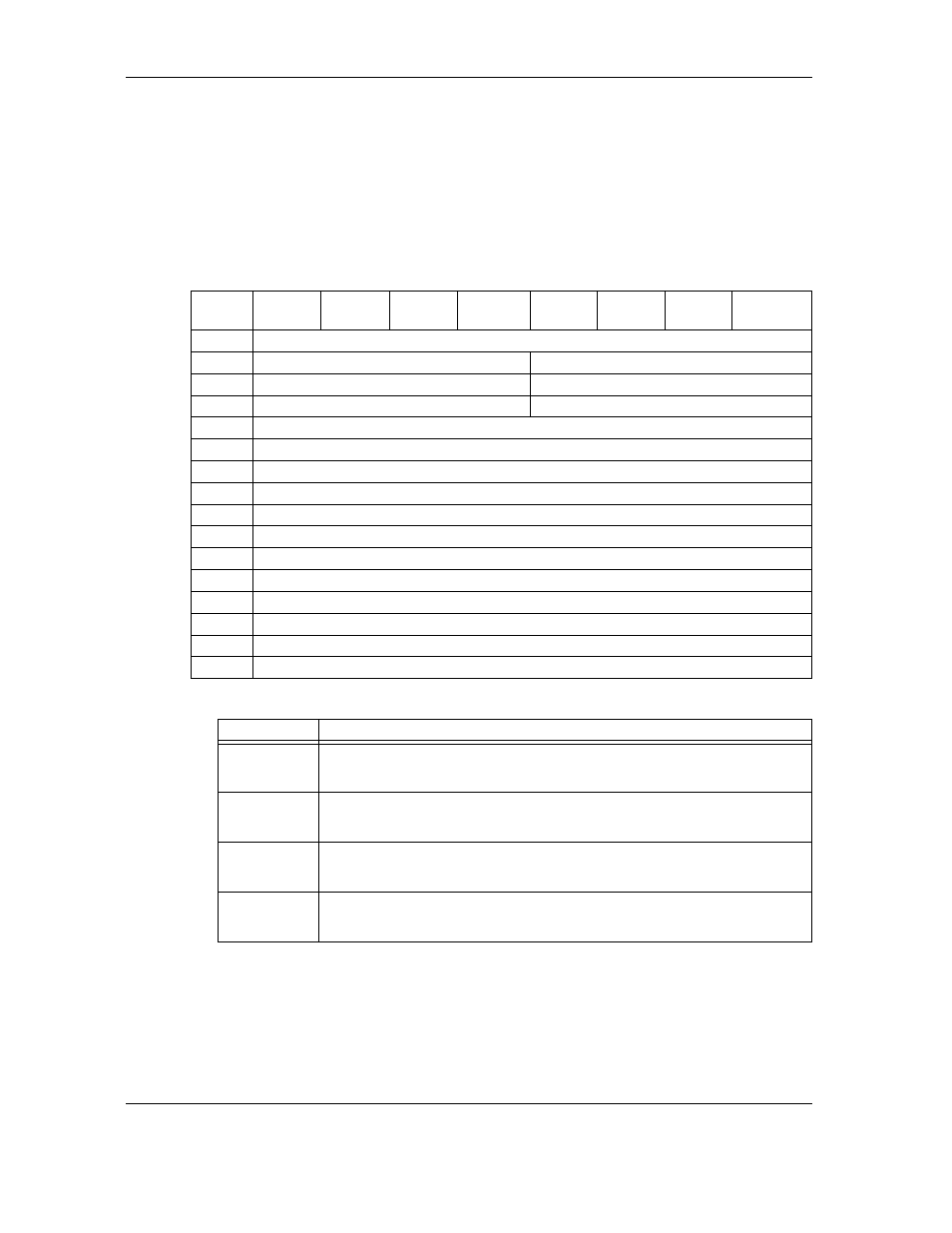
Margin Control Subpage (Sub Page 1 of Mode Page 19)
The Margin Control subpage (see Table 5-74) contains parameters that set and report
margin control values for usage between the initiator/target pair on subsequent
synchronous and paced transfers.
A MODE SELECT command will return the current settings for the initiator/target
pair. Fields that are not implemented will be reported as zero.
Table 5-74
Margin Control Subpage (01h)
Table 5-75
Field Descriptions
Bit
Byte
7
6
5
4
3
2
1
0
0
Reserved
1
Driver Strength
Reserved
2
Drive’s Asymmetry
Driver Precompensation
3
Drive’s Slew Rate
Reserved
4
Reserved
5
Reserved
6
Reserved
7
Vendor Specific
8
Reserved
9
Reserved
10
Reserved
11
Reserved
12
Reserved
13
Reserved
14
Reserved
15
Reserved
Field
Description
Driver
Strength
The DRIVER STRENGTH field indicates the relative amount of driver source cur-
rently used by the driver. The Driver Strength field affects both the strong and week
drivers. A larger value indicates more driver source current.
Driver Pre-
compensation
The DRIVER PRECOMPENSATION field indicates the relative difference between
the weak driver and the strong driver amplitudes when precompensation is enabled.
A larger value indicates a larger difference between the weak and strong amplitudes.
Driver
Asymmetry
The Driver Asymmetry field indicates the relative difference between the amplitudes
of asserted and negated signals launched from the driver. A larger value indicates a
relatively stronger asserted signal compared to the negated signal.
Driver Slew
rate
The DRIVER SLEW RATE field indicates the relative difference between the asser-
tion and negation magnitudes divided by the rise or fall time. A larger value indicates
a faster slew rate.