Tv-out connector: jtv1, Irda infrared module header: irda1, I2c bus connector: j1 – MSI FUZZY CX700D User Manual
Page 33
2-15
Hardware Setup
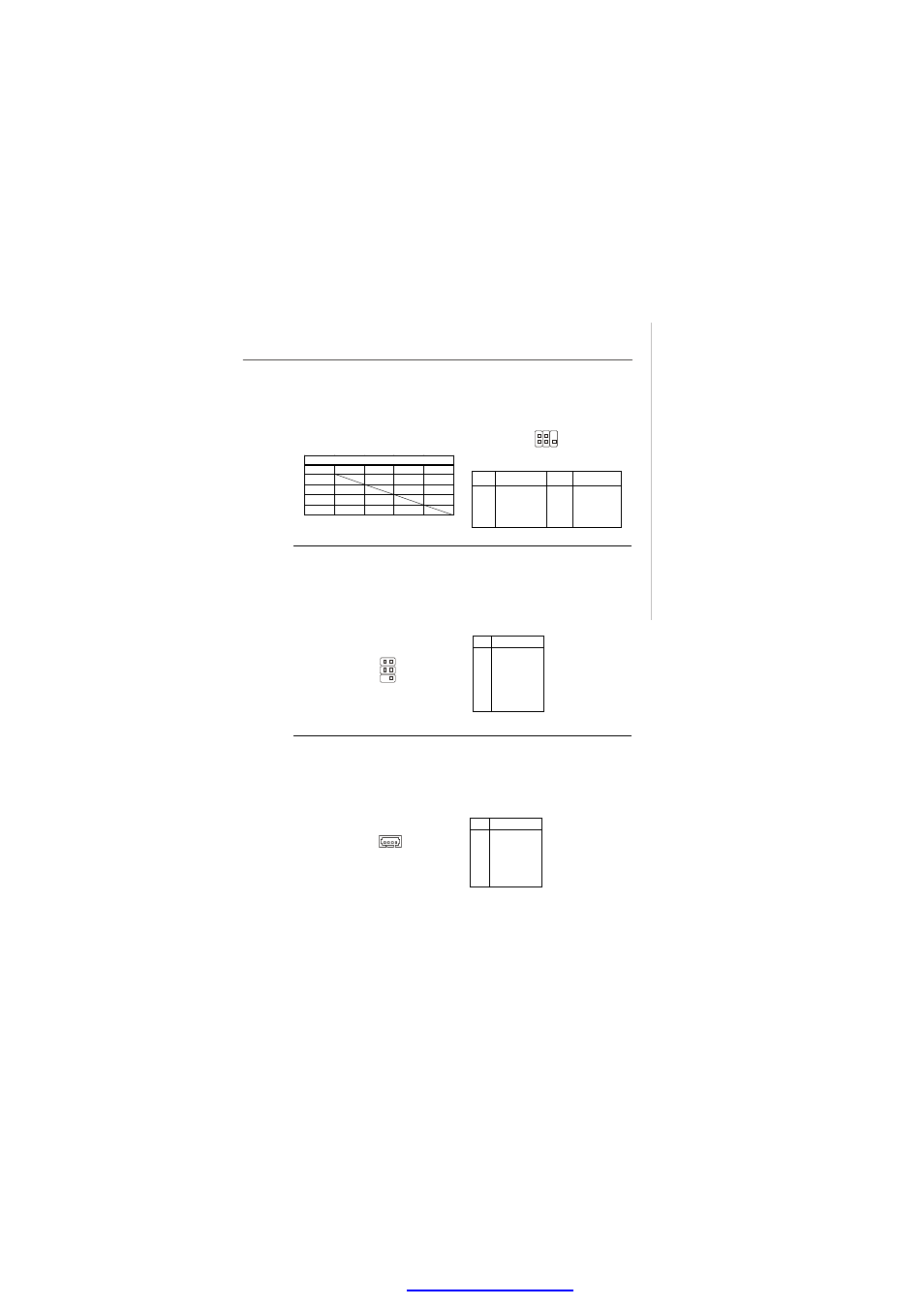
Pin
Description
Pin
Description
1
TVGND
2
LCVBS
3
LY
4
TVGND
5
LC
6
Key (no pin )
JTV1 Pin Definition
TV-Out Connector: JTV1
The mainboard provides a TV-Out connector.
IrDA Infrared Module Header: IRDA1
The connector allows you to connect to IrDA Infrared module. You must configure the
setting through the BIOS setup to use the IR function. IRDA1 is compliant with Intel
®
Front Panel I/O Connectivity Design Guide.
JTV1
1
5
2
IRDA1
6
5
2
1
Pin
Signal
1
NC
2
Key (no pin)
3
VCC5
4
GND
5
IRTX
6
IRRX
Pin Definition
I2C Bus Connector: J1
The mainboard provides one I2C (also known as I
2
C) Bus connector for users to
connect System Management Bus (SMBus) interface.
Pin
Signal
1
VCC5F
2
SMBCLK
3
GND
4
SMBDATA-
Pin Definition
J1
4
1
CRT
DVI
LVDS
TV OUT
CRT
V
V
X
DVI
V
V
V
LVDS
V
V
V
TV OUT
X
V
V
Display Matrix
V : Support
X : No Support
PDF created with pdfFactory Pro trial versi