System components, The ip extender cables, Ip extender front panel – Minicom Advanced Systems Smart IP Extender User Manual
Page 8: Figure 3 illustrates the ip extender front panel
SMART IP EXTENDER
7
IPMI Version 1.5 - defines a serial connection to access certain system parameters
and perform system actions like powering down or a hard reset. Modern server
systems, supporting the IPMI V1.5 specification, provide a mode where the
externally available COM2 serial connection can be configured as a system
management port (sometimes called an emergency management port). IP Extender
may use this port in order to enable remote system management operations.
5. System components
• 1 IP Extender Extender box
• Cables (illustrated below)
• Power cord
• Marketing & Documentation CD
• Optional IPMI Option. This is a serial cable for connecting the IP Extender
and an IPMI V1.5 compliant serial management port on the remote system.
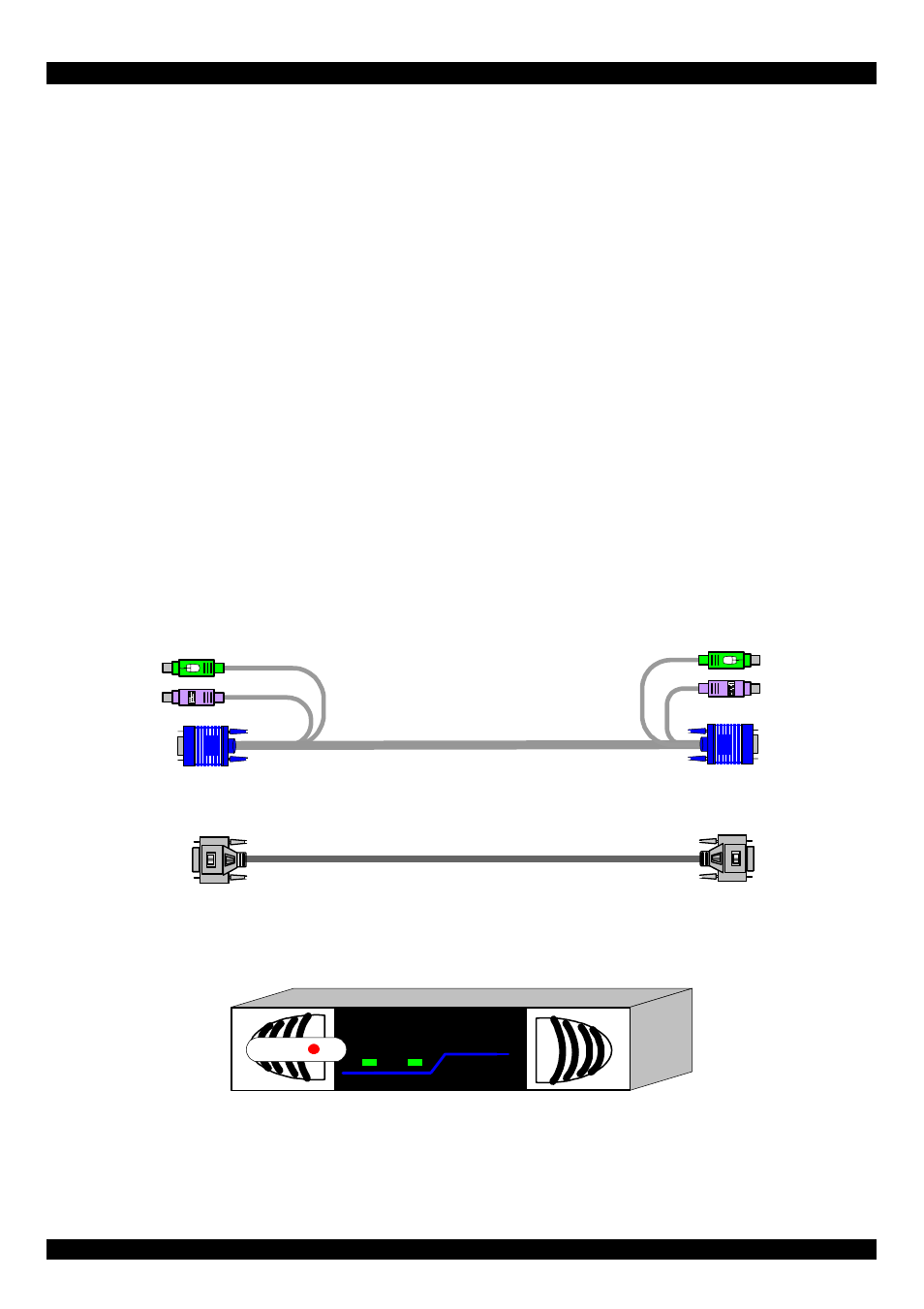
6. The IP Extender cables
The IP Extender package contains the following cables.
3 in 1 CPU cable
Null Modem cable
7. IP Extender front panel
Figure 3 illustrates the IP Extender front panel.
MINIC
O
M
Activity
SMART IP
Extender
System OK
Figure 3 Front panel