Warning, Danger – McCulloch Cabrio 115249726 User Manual
Page 6
6
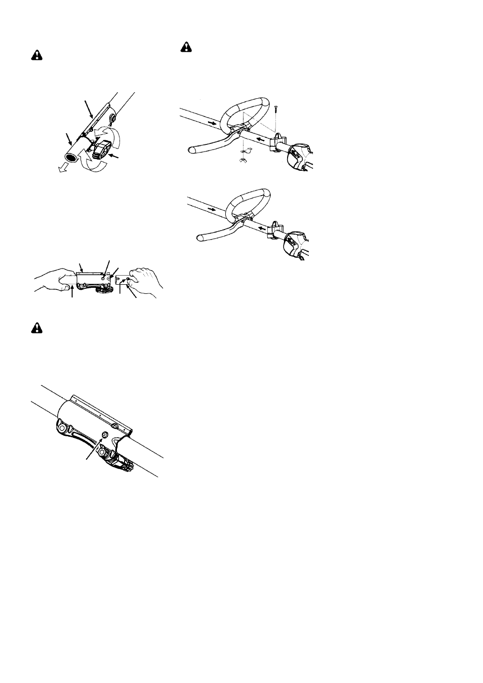
INSTALLING TRIMMER
ATTACHMENT
WARNING:
When installing attach-
ment, place the unit on a flat surface for stabil-
ity.
1. Loosen the coupler by turning the knob
counterclockwise.
Shipping
protector
Coupler
Knob
LOOSEN
TIGHTEN
2. Remove shipping protector from coupler.
3. Remove the shaft cap from the attachment
(if present).
4. Position locking/release button of attach-
ment into guide recess of coupler.
5. Push the attachment into the coupler until
the locking/release button snaps into the
primary hole.
6. Before using the unit, tighten the knob se-
curely by turning clockwise.
Coupler Primary Hole
Upper
Shaft
Locking/
Release
Button
Attachment
Guide Recess
WARNING:
Make sure the locking/
release button is locked in the primary hole
and the knob is securely tightened before op-
erating the unit. All attachments are designed
to be used in the primary hole unless otherwise
stated in the applicable attachment instruction
manual. Using the wrong hole could lead to seri-
ous injury or damage to the unit.
Locking/Release
Button in Primary Hole
For optional attachments, see the ASSEMBLY
section of the applicable attachment instruction
manual.
ATTACHING THE HANDLE
DANGER:
To avoid serious injury, the
barrier portion of the handle must be installed as
shown to provide a barrier between operator
and the spinning blade.
1. Position the loop handle on the shaft. Note
that the handle must be mounted between
the arrows on the shaft.
2. Install the bolt, securing plate and wing
nut as shown in the illustration.
3. Make a final adjustment of the handle to a
comfortable working position. Tighten the
wing nut.
ASSEMBLY OF SHOULDER STRAP
Proper shoulder strap and handlebar adjust-
ments must be made with the engine com-
pletely stopped before using unit.
1. Insert your right arm and head through the
shoulder strap and allow it to rest on your
left shoulder. Make sure the hook is to the
right side of your waist.
NOTE:
A one-half twist is built in the shoul-
der strap to allow the strap to rest flat on the
shoulder.
2. Adjust the strap, allowing the hook to be
about 15 cm below the waist.
3. Fasten the strap hook to the clamp located
between the trigger handle and the handle-
bar clamp base and lift the tool to the operat-
ing position.
4. Try on shoulder strap and adjust for fit and
balance before starting the engine or be-
ginning a cutting operation.
NOTE:
It may be necessary to relocate the
shoulder strap clamp on the shaft for proper
balancing of unit.
TO RELOCATE SHOULDER STRAP
CLAMP:
1. Loosen and remove both clamp screws.
2. Place the upper shoulder strap clamp
over the shaft.
3. Position the lower shoulder strap clamp
under the shaft and align the upper and
lower clamp screw holes.