Venting installation – Monessen Hearth 6000DV User Manual
Page 21
42D0200
21
9
1
/
2
"
(241mm)
11
1
/
2
"
(292mm)
4
3
/
8
"
(121mm)
7
1
/
2
"
(190mm)
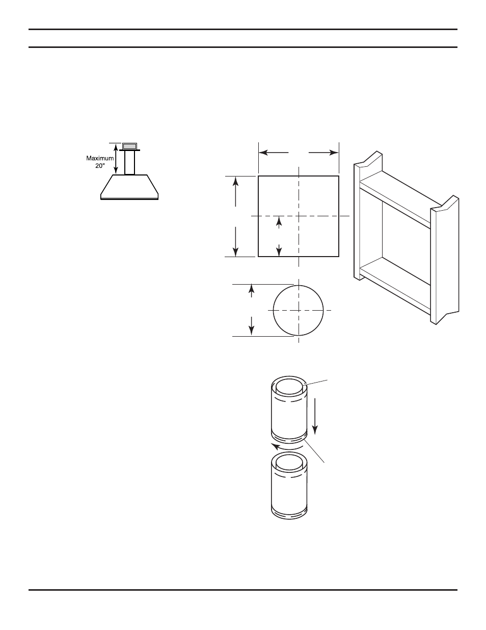
REAR WALL VENT INSTALLATION
When installed as a rear vent unit this appliance may be vented directly to a termination located on the rear wall behind
the appliance
• The maximum horizontal distance between the rear of the appliance and the outside face of the rear wall is 20" (508 m).
See Figure 19.
• Only one 45° elbow is allowed in these installations.
VENTING INSTALLATION
Note: Horizontal runs of vent
must be supported every three
feet (914mm). Use wall straps
for this purpose.
Figure 21 - Rigid Vent Pipe Connections
Female
Locking Lugs
Male Slots
Figure 20 - Vent Opening Requirements
1. Locate and cut the vent opening in the wall. For
combustible walls first frame in opening.
Combustible Walls:
Cut a 11
1
⁄
2
"H x 9
1
⁄
2
" W (292mm
x 24mm) hole through the exterior wall and frame as
shown. See Figure 20.
Noncombustible Walls:
Hole opening should be
7
1
⁄
2
" (190mm) in diameter.
2. Rigid vent pipes and fittings have special twist-lock
connections. Assemble the desired combination of
pipe and elbows to the appliance adaptor with pipe
seams oriented towards the wall or floor.
Twist-lock Procedure:
The female ends of the pipes
and fittings have three locking lugs (indentations).
These lugs will slide straight into matching slots on
the male end of adjacent pipes and fittings. Push the
pipe sections together and twist one section clockwise
approximately one-quarter turn until the sections are
fully locked. See Figure 21.
3. Attach vent pipe assembly
thy
!
3y*
M