Detailed description of software, Detailed description of hardware – Maxim Integrated MAX5865 User Manual
Page 4
20) Connect the -5.0V terminal of the bipolar power
supply to the VEE pad.
21) Turn on the five power supplies.
22) Probe resistor pad R28 with an oscilloscope and
adjust potentiometer R13 to set the clock duty cycle
to 50%.
23) Start the MAX5865 program by opening its icon in
the Start menu.
24) Click on the
Xcvr control command to set the
MAX5865 in receive/transmit (transceiver) opera-
tional mode.
25) Enable the clock function generator (HP 8662A).
Set the clock function generator output power to
2.4V
P-P
(11.6dBm) and the frequency (f
CLK
) to
greater than 22MHz but less than or equal
to 40MHz.
26) Enable the function generators.
27) Set the IA function-generator output signal to
1.024V
P-P
and the frequency to ≤ f
CLK
/2.
28) Set the QA function-generator output signal to
1.024V
P-P
and and the frequency to ≤ f
CLK
/2.
29) Use the logic analyzer to analyze the 8-bit ADC dig-
ital output. The IA channel digital data is available
on the falling edge of the clock. The QA digital data
is available on the rising edge of the clock. Ensure
that the ADC input is not overdriven by observing
the output digital codes and adjusting the input sig-
nal level for code of -0.5dB full scale.
30) Enable the digital pattern generator. Program the
digital pattern generator to transmit the digital data
for the DAC I channel on the falling edge of the
clock and transmit the digital data for the Q channel
on the rising edge of the clock.
31) Connect the spectrum analyzers to the ID and QD
SMA connectors to analyze the analog outputs.
32) Use the spectrum analyzer to analyze the analog
output spectrum or view the analog output wave-
forms using an oscilloscope.
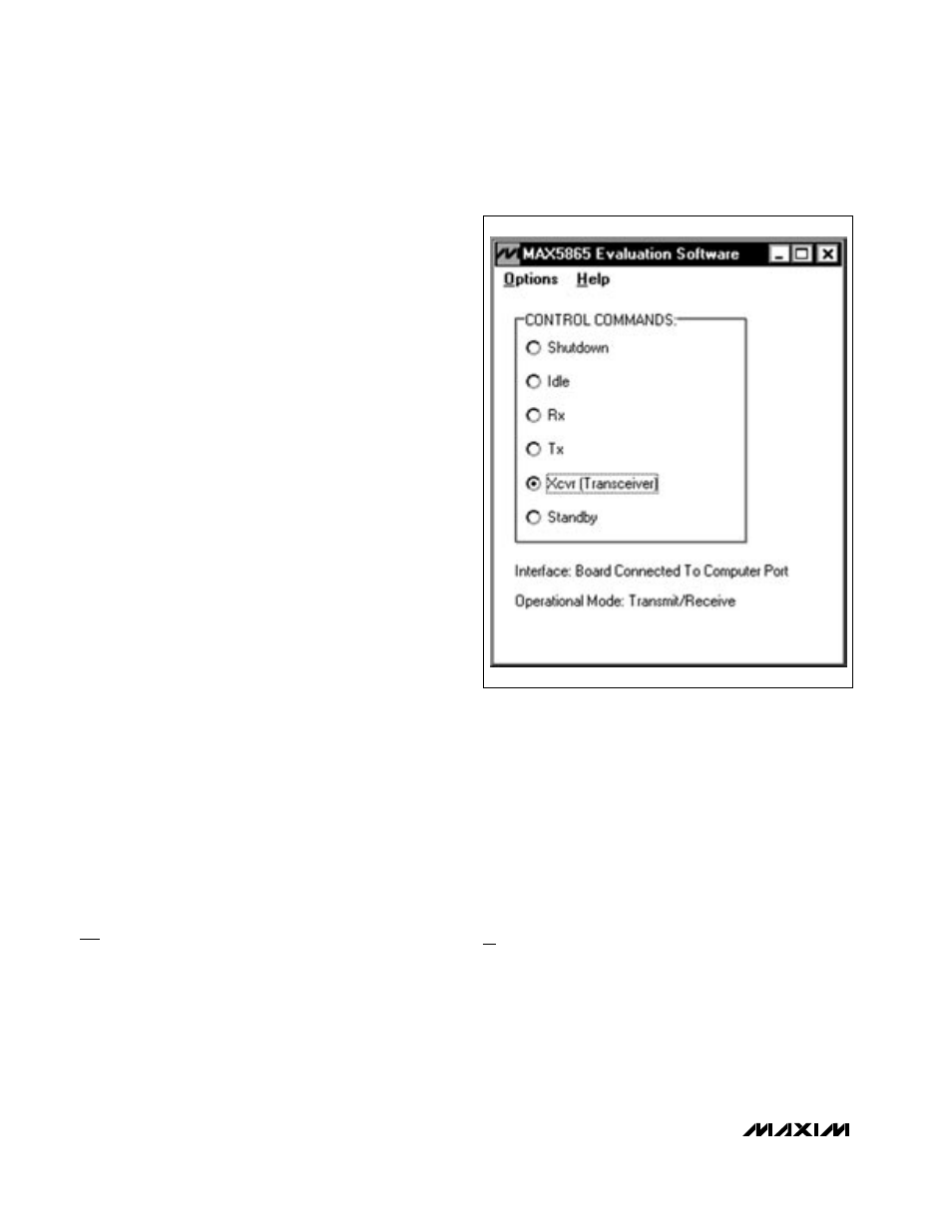
Detailed Description of Software
The evaluation software’s main window (shown in
Figure 1) can be used to program the MAX5865 to one
of the six operational modes: shutdown, idle, receive
(Rx), transmit (Tx), transceiver (Xcvr), and standby.
Click one of the buttons to program the MAX5865 to the
desired operational mode after power has been
applied to the EV kit. Use the keyboard arrow keys to
cycle through the control commands. See Table 1 for
the description of each operational mode.
The MAX5865 evaluation software uses a 3-wire bit-bang-
ing interface that is compatible with SPI
TM
/ QSPI
TM
/
MICROWIRE
TM
/DSP interfaces to program the MAX5865
through the parallel port on the computer. Table 1 lists the
byte command for each operational mode.
Detailed Description of Hardware
The MAX5865 EV kit is a fully assembled and tested cir-
cuit board that contains all the components necessary to
evaluate the performance of the MAX5865, MAX5864, or
Evaluates: MAX5863/MAX5864/MAX5865
MAX5865 Evaluation Kit
4
_______________________________________________________________________________________
SPI and QSPI are trademarks of Motorola, Inc.
MICROWIRE is a trademark of National Semiconductor Corp.
Figure 1. MAX5865 EV Kit Software Main Window