Miller Electric Millermatic 180 User Manual
Page 31
.
A complete Parts List is available on-line at www.MillerWelds.com
OM-225 311 Page 27
227 931-H
H
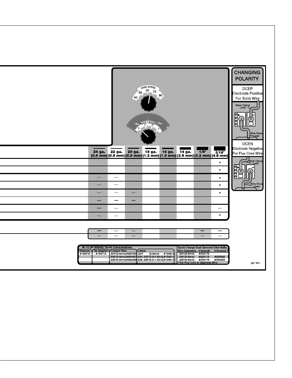
Manual Setup
Refer to chart below to select Voltage and Wire Speed based
on thickness of metal being welded.
2. Number on left of
slash is Voltage
Knob Setting.
(Example: 4 / 65)
1. Number on right
of slash is Wire
Speed Knob Setting.
(Example: 4 / 65)
10/90
10/65
10/80
10/60
10/65
10/50
10/50
10/75
5.5/60
5.5/80
7/80
5.5/60
4.5/45
5/55
4/45
3/50
3/40
6/75
6/60
6.5/50
4.5/70
5.5/65
5.5/45
3/40
3/35
4/65
4/45
4/35
5/40
2.5/32
3/40
3/50
2/40
2/32
10/95
7/95
7/70
5/50
4.5/50
4/40
4.5/50
2/35
5/60
A
ut
o−
Se
t
10/100
3/90
3/90
10/90
3/75
3/70
THIC
KN
E
S
S
t
MATERI AL
This manual is related to the following products: