Work cable routing inside unit, Process/polarity table, Changing polarity – Miller Electric Millermatic 180 User Manual
Page 17: 3. work cable routing inside unit, 4. process/polarity table, 5. changing polarity
.
A complete Parts List is available on-line at www.MillerWelds.com
OM-225 311 Page 13
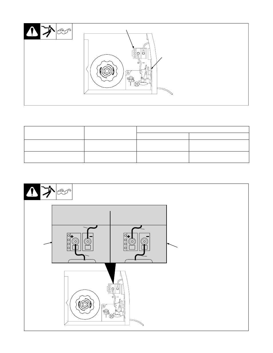
4-3.
Work Cable Routing Inside Unit
Ref. 802 982-A
1
Work Cable
2
Output Terminal Block
Insert work cable through opening
in front panel and route along back
of front panel to output terminal
block.
Close door.
2
1
4-4.
Process/Polarity Table
Process
Polarity
Cable Connections
Process
Polarity
Cable To Gun
Cable To Work
GMAW − Solid wire with shield-
ing gas
DCEP − Reverse polarity
Connect to positive (+) out-
put terminal
Connect to negative (−) output
terminal
FCAW − Self-shielding wire −
no shielding gas
DCEN − Straight Polarity
Connect to negative (−)
output terminal
Connect to positive (+) output
terminal
4-5.
Changing Polarity
1
Lead Connections For Direct
Current Electrode Positive
(DCEP)
2
Lead Connections For Direct
Current Electrode Negative
(DCEN)
Always read and follow wire
manufacturer’s recommended
polarity, and see Section 4-4.
Close door.
1
Ref. 203 501 / Ref. 802 982-
2
C H A N G IN G P O L A R IT Y
DCEP
Electrode POSITIVE
FOR SOLID WIRE
DCEN
Electrode Negative
Flux Core Wire
WorkClamp
Lead
Wire Drive
Lead
WorkClamp
Lead
Wire Drive
Lead
C H A N G IN G P O L A R IT Y
DCEP
Electrode Positive
FOR SOLID WIRE
DCEN
Electrode Negative
Flux Core Wire
WorkClamp
Lead
Wire Drive
Lead
WorkClamp
Lead
Wire Drive
Lead
.
Connection hardware must be tightened with proper tools. Do not
just hand tighten hardware. A loose electrical connection will cause
poor weld performance and excessive heating at the terminal block.