Pin description table – Maxtor DIAMONDMAX 91536H2 User Manual
Page 26
AT INTERFACE DESCRIPTION
5 – 2
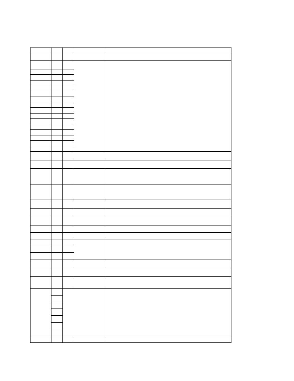
Pin Description Table
PIN NAME
PIN
I/O
SIGNAL NAME
SIGNAL DESCRIPTION
RESET -
01
I
Host Reset
Reset signal from the host system. Active during power up and inactive after.
DD0
17
I/O
Host Data Bus
16 bit bi-directional data bus between host and drive. Lower 8 bits used for
register and ECC byte transfers. All 16 bits used for data transfers.
DD1
15
I/O
DD2
13
I/O
DD3
11
I/O
DD4
09
I/O
DD5
07
I/O
DD6
05
I/O
DD7
03
I/O
DD8
04
I/O
DD9
06
I/O
DD10
08
I/O
DD11
10
I/O
DD12
12
I/O
DD13
14
I/O
DD14
16
I/O
DD15
18
I/O
DMARQ
21
O
DMA Request
This signal is used with DMACK for DMA transfers. By asserting this signal, the
drive indicates that data is ready to be transfered to and from the host.
DIOW -
STOP
23
I
Host I/O Write
Rising edge of Write strobe clocks data from the host data bus to a register on
the drive.
DIOR -
HDMARDY
-
HSTROBE
25
I
Host I/O Read
Read strobe enables data from a register on the drive onto the host data bus.
DMA ready during UltraDMA data in bursts.
Data strobe during UltraDMA data out bursts.
IORDY
DDMARDY
-
DSTROBE
27
O
I/O Channel Ready
This signal may be driven low by the drive to insert wait states into host I/O
cycles.
DMA ready during UltraDMA data out bursts.
Data strobe during UltraDMA data in bursts.
CSEL
28
Cable Select
Used for Master/Slave selection via cable. Requires special cabling on host
system and installation of Cable Select jumper.
DMACK -
29
I
DMA Acknowledge
This signal is used with DMARQ for DMA transfers. By asserting this signal, the
host is acknowledging the receipt of data or is indicating that data is available.
INTRQ
31
O
Host Interrupt
Request
Interrupt to the host asserted when the drive requires attention from the host.
IOCS16
32
Device 16 bit I/O
Obsolete
PDIAG -
34
I/O
Passed Diagnostic
Output by drive when in Slave mode; Input to drive when in Master mode.
DA0
35
I
Host Address Bus
3 bit binary address from the host to select a register in the drive.
DA1
33
I
DA2
36
I
CS0 -
37
I
Host Chip Select 0
Chip select from the host used to access the Command Block registers in the
drive. This signal is a decode of I/O addresses 1F0 - 1F7 hex.
CS1 -
38
I
Host Chip Select 1
Chip select from the host used to access the Control registers in the drive. This
signal is a decode of I/O addresses 3F6 - 3F7 hex.
DASP -
39
I/O
Drive Active/Drive
1 Present
Time-multiplexed, open collector output which indicates that a drive is active, or
that
device 1 is present.
GND
02
N/A
Ground
Signal ground.
19
22
24
26
30
40
KEY
20
N/A
Key
Pin used for keying the interface connector.