Venting installation – Monessen Hearth Direct Vent Gas Fireplace BDV500 User Manual
Page 18
18
54D0700
9
1
/
2
"
(241mm)
9
1
/
2
"
(241mm)
3
3
/
4
"
(92mm)
7
1
/
2
"
(190mm)
Maximum
20"
Top View Flat Installation
REAR (THROUGH THE WALL) APPLICATIONS
When installed as a rear vent unit this appliance may be vented directly to a termination located on the rear wall behind
the appliance
• The maximum horizontal distance between the rear of the appliance and the outside of termination is 20" (508 m). See
Figure 14.
• Only one 45° elbow is allowed in these installations.
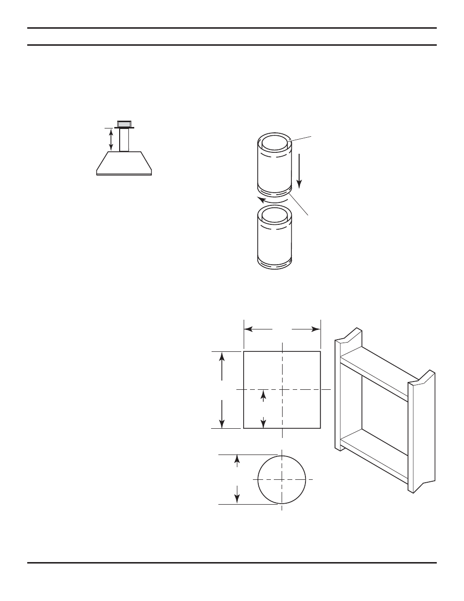
VENTING INSTALLATION
Sealant is not required to assemble BDV/DVB
fireplace venting. Do not use silicone sealant at
the flue exhaust connections.
1. Find the pipe section’s direction label. The
label arrow shall be pointed away from the
firebox and toward the termination. Firmly
insert the initial rigid section/elbow into the
firebox outer collar. Simpson “GS” and Selkirk
“DT” outer walls are hemmed and will snap
into the collar’s tabs. Attach Simpson’s Direc-
tVent Pro by fully inserting into the collar and
securing with self tapping screws. The screws
shall only penetrate the flue outer wall.
Refer to vent manufacturer’s installation
instructions to properly assemble flue.
2. Locate and cut the vent opening in the
wall. For combustible walls first frame in
opening.
Combustible Interior Walls:
Cut a 11
1 2
"H
x 9
1 2
" W hole through the interior wall.
Combustible Exterior Walls:
Cut a 9
1 2
"H
x 9
1 2
"W square hole through the exterior
wall frame. See Figure 16.
Noncombustible Walls:
Hole opening
should be 7
1 2
" (190mm) in diameter.
3. The center of the hole should line up with the
center line of the horizontal rigid vent pipe
end. Pipe shall always run level or uphill on
horizontal runs. Never run pipe down hill. See
Figure 16.
Figure 14 - Rear Vent Application,
Maximum Horizontal Distance
Figure 16 - Exterior Wall Framing Dimensions
Note: Horizontal runs of vent
must be supported every three
feet (914mm). Use wall straps
for this purpose.
Figure 15 - Rigid Vent Pipe Connections
Female
Locking Lugs
Male Slots