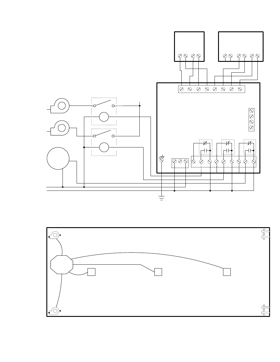
Revision 0.07 6, Figure 1-1 system wiring diagram, Engineer and architect specifications – Macurco DVP-120 User Manual
Page 6
Revision 0.07
6
CM-2B
D
C
B
-
A
+
output
power
coil
coil
Exhaust Fans
120 VAC
ALARM
120 VAC
Power
Main Fan Power
STARTER RELAYS
120 VAC COILS
MACURCO DVP-120
GAS DETECTION AND
VENTILATION CONTROL PANEL
exhaust fan
exhaust fan
CM-2B,
CM-3 or
SS102HC-1
CM-2B,
CM-3 or
SS102HC-1
CM-2B,
CM-3 or
SS102HC-1
Air inlet:
door, damper,
louvier
Air inlet:
door, damper,
louvier
space sensors equally,
mount 5 feet above floor
Typical layout in Parking Garage
DVP-120
panel
NOTE
1. Typical coverage for a CO sensor is 5000 sq. ft., 900 sq. ft. for combustible gasses.
Extra sensors may be needed near areas where people work, such as toll booths.
2. Macurco provides only the control panels and sensors. Fans, relays, and other devices are provided by the contractor.
3. See the appropriate building code for the size of fans and air changes per unit of time.
NOTE:
1. Power connections at the sensor are non-polarized.
2. DVP-120 connections are representative of J7, J8, J10, J11, J13 and J14.
ENGINEER AND ARCHITECT SPECIFICATIONS
Gas detection and exhaust fan control is provided by a Macurco DVP-120
system. This System will use CM-2B or CM-3 Carbon Monoxide (CO) to
current transducers, ND-2 Nitrogen Dioxide to current transducers or GT-
11A Combustible Gas to current transducers. Each transducer will measure
the level of the target gas and provide this information to the DVP-120 over
a 4-to-20 mA current loop. The Transducers are mounted in a standard 6"
x 6" electrical enclosure, and operate on low voltage (24 VDC).
All power and signal connections for the transducers are provided from the
DVP-120 control panel, via unshielded four conductor cable. The DVP-120
control panel provides three relays which can be used for ventilation fan
control or alarm signaling . These relays (SPDT - Form C) are for pilot duty
only, capable of switching 10 amp loads up to 240 VAC .
D
C
-
+
mA
output
power
V
output
-
+
GT-11A
Gnd
L
N
Panel Power
120/250 VAC
J4
1
3
J7, J8,
J10, J11,
J13, L14
J2
4
- Strobe
3
+ Strobe
2
- Horn
1
+ Horn
1
8
7
6
5
4
3
2
+24 VDC
+24 VDC
+24 V RET
+24 V RET
+I LOOP
+I LOOP
-I LOOP
-I LOOP
Relay 1
Relay 2
Relay 3
N.C.
N.C.
N.C.
N.O.
N.O.
N.O.
COM
COM
COM
3
8
9
4
5
6
1
2
7
J2
Figure 1-1 System Wiring Diagram