Typical application, 8chapter 1 - introduction to the multivoip, Multi-tech systems, inc. multivoip user guide – Multi-Tech Systems MVP120 User Manual
Page 8
8
Chapter 1 - Introduction to the MultiVOIP
Multi-Tech Systems, Inc. MultiVOIP User Guide
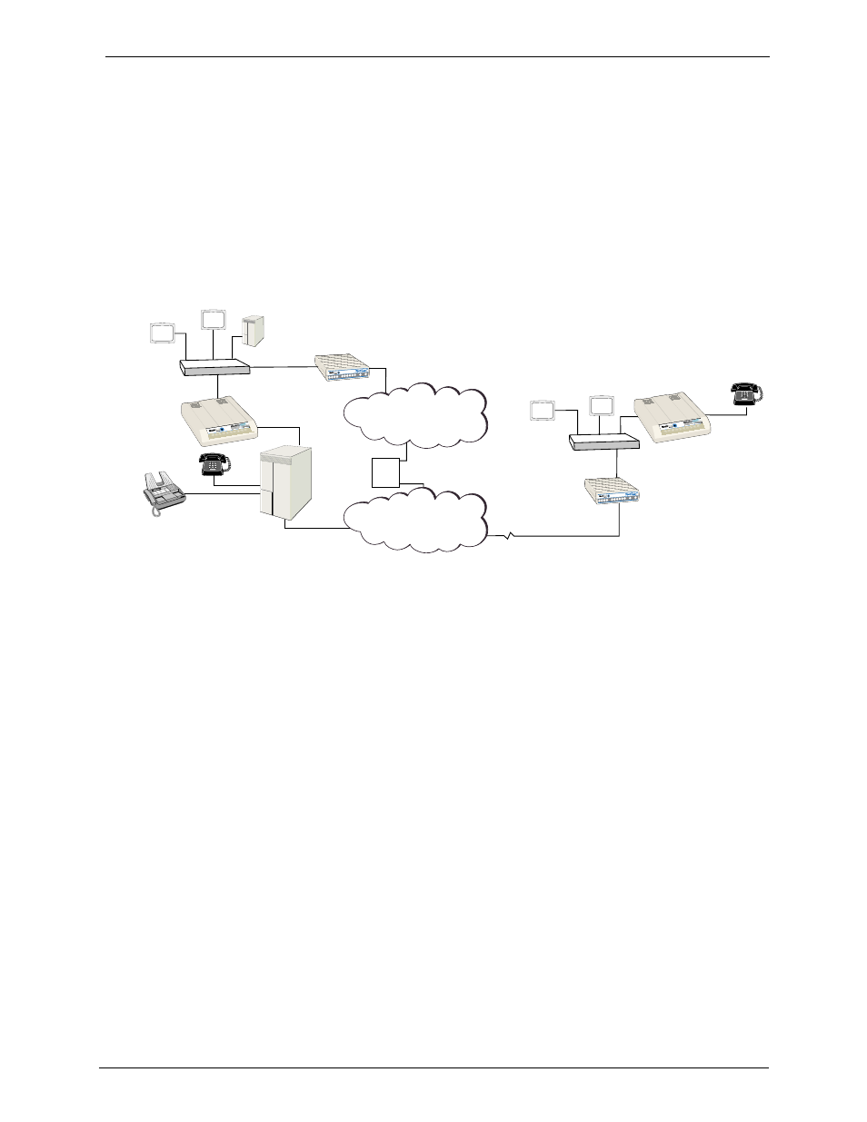
Typical Application
Before VOIP (Voice Over IP) technology existed, a sales office used a data connection to the
Internet and a voice connection to the public telephone network. Now, with VOIP, the two
networks can be tied together. To accomplish this a Sales Office MultiVOIP is connected
between the public telephone network and the data network as shown in the typical
application below. The Sales Office MultiVOIP is going to be set up as the master MultiVOIP
and the MultiVOIP at the Remote Sales Office is going to be set up as the slave MultiVOIP.
With this approach, the person at the Remote Sales Office can pick up the telephone and dial
the Sales Office MultiVOIP and, after a second dial tone, can call anyone in the Sales Office,
or dial 9 for outside line and call anyone in the calling area as if they were at the Sales Office.
PSTN Connection
(T1/E1, PRI, etc.)
#201
101
Remote Sales
Office
HUB
Workstation
Workstation
LAN
MVP110
IP Address 206.25.124.120
Mask 255.255.255.240
ProxyServer
IP Address 206.25.124.110
Mask 255.255.255.240
ProxyServer Static IP
Address 209.96.211.90
Internet/Intranet
IP Network
ISP
PSTN
Router
IP Address 201.22.122.1
Mask 255.255.255.128
Sales Office
HUB
P
B
X
Web Server
Workstation
Workstation
MultiVOIP MVP120
IP Address
201.22.122.118
Mask 255.255.255.128
LAN
Analog Connections
Channel 1: FXO
512-4122
512-4123
4124
Fax
Typical VOIP Application
To set up this VOIP network, an MVP120 at the Sales Office is connected between the data
network and the sales office telephone switch (PBX). To connect the MVP120 to the data
network, an Ethernet cable is connected to the Ethernet port on the unit and the other end is
plugged into a hub on the data network. On the PBX side, one phone cord is connected to
the FXO jack on the back of the MVP120 and attached to an FXO port on the phone switch.
The line on the PBX occupies phone extension 4124.
To set up a remote sales office, connect the Ethernet jack on an MVP110 to the hub, and
connect (by a phone cord) a telephone to the FXS jack on the MVP110.
To configure the MVP120, the COM port of a PC is connected to the Command port on the
MVP120. The configuration software is based on a standard Windows Graphical User
Interface (GUI) which simplifies your selection process to a single parameter group within a
dialog box. For example, your LAN IP parameters are contained on a single dialog box. You
can configure your network IP address and mask for the MVP120 and the gateway address
for the corporate router on the same dialog box.
After your network configuration is complete, then you can develop your VOIP phone
directory database. This database will be developed on the Sales Office MultiVOIP and sent
out to the Remote Sales Office.
You will need to add the phone numbers to the phone directory database. Before you set up
the phone directory database, you need to consider how the database is going to be used:
Are you going to have an H.323 Gatekeeper setup your call sessions,
or
Are you going to control your call sessions using the proprietary phone book?