Milwaukee 0300-20 User Manual
Page 5
9
8
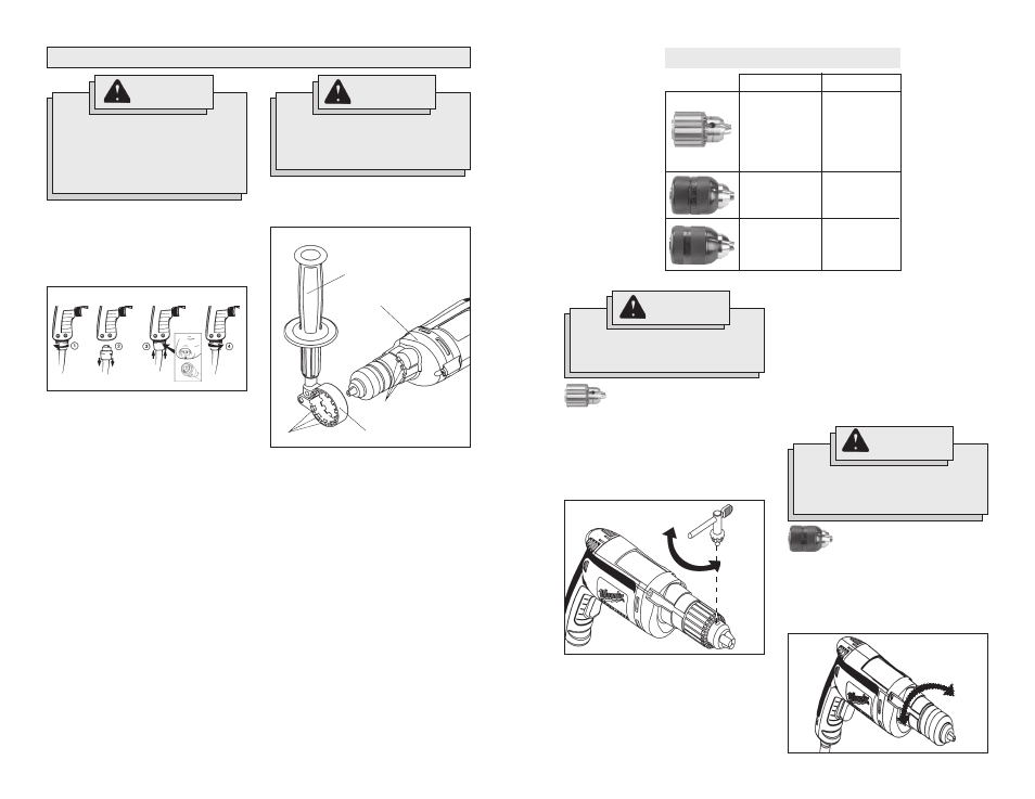
Double Sleeve Keyless
Chuck (Fig. 4, 5, & 6)
These tools are equipped with a hand tight-
ening keyless chuck. Always unplug the
tool before installing or removing bits.
1. To open the chuck jaws, hold the collar
and turn the sleeve counterclockwise
(Fig. 4).
Keyed Chuck (Fig. 3)
These tools are equipped with a chuck tight-
ened using a key. Always unplug the tool
before installing or removing bits.
1. To open the chuck jaws, place the
chuck key in one (1) of the three (3)
holes located on the chuck. Turn the
key counterclockwise (Fig. 3).
WARNING!
To reduce the risk of injury, al-
ways remove the chuck key from
the chuck after each use.
Be sure the bit shank and chuck jaws
are clean. Dirt particles may prevent
the bit from lining up properly.
2. When using drill bits, insert the bit into
the chuck. Center the bit in the chuck
jaws and lift it about 1/16" off of the
bottom. Tighten the chuck jaws by hand
to align the bit.
Fig. 3
When using screwdriver bits, insert the
bit far enough for the chuck jaws to
grip the bit shank. Tighten the chuck
jaws by hand to align the bit.
3. To close the chuck jaws, place the
chuck key in each of the three holes in
the chuck. Turn the chuck key clock-
wise (Fig. 3). Tighten securely.
4. To remove the bit, insert the chuck key
into one of the holes in the chuck. Turn
the chuck key counterclockwise.
Installing and Removing Bits
CHUCK IDENTIFICATION
Chuck Type
Drill Cat. No.
0100-20
0101-20
0200-20
0299-20
0300-20
Keyed
0202-20
0302-20
Single sleeve
Keyless
Double sleeve
Keyless
0201-20
Tighten
Loosen
Fig. 4
Loosen
Tighten
WARNING!
To reduce the risk of injury, do not
grasp the bit while the chuck is
rotating or while the bit is falling
from the chuck.
WARNING!
TOOL ASSEMBLY
To reduce the risk of injury,
always unplug tool before attach-
ing or removing accessories
or making adjustments. Use only
specifically recommended acces-
sories. Others may be hazardous.
Removing and Replacing Quik-Lok
®
Cords (Fig. 1) (Cat. No. 0100-20,
0101-20, 0202-20, 0302-20
MILWAUKEE's exclusive Quik-Lok
®
Cords
provide instant field replacement or
substitution.
Fig. 1
1. To remove the Quik-Lok
®
Cord, turn the
cord nut 1/4 turn to the left and pull it
out.
2. To replace the Quik-Lok
®
Cord, align the
connector keyways and push the con-
nector in as far as it will go. Turn the
cord nut 1/4 turn to the right to lock.
Adjusting the Side Handle (Fig. 2)
(Cat. No. 0200-20, 0202-20, 0299-20,
0300-20, 0302-20)
1. Turn the side handle counterclockwise
to loosen.
2. Slide the side handle assembly forward
over the chuck and rotate to the de-
sired angle.
3. Slide the side handle back to the
gearcase and position the locking keys
into the detents. The locking keys help
prevent the handle from slipping.
NOTE: The side handle ring must clear
the chuck.
4. Turn the side handle clockwise to
tighten.
NOTE: Always use the side handle for
best control.
WARNING!
To reduce the risk of injury, al-
ways use a side handle when us-
ing this tool. Always brace and
hold securely.
Gearcase
Side handle ring
Side handle
Locking keys
Detents
Fig. 2