Front panel connector: jfp1, Front panel i/o connectivity design guide, Chapter 2 2-20 – MSI G52-MA00542 User Manual
Page 32: Jfp1
Chapter 2
2-20
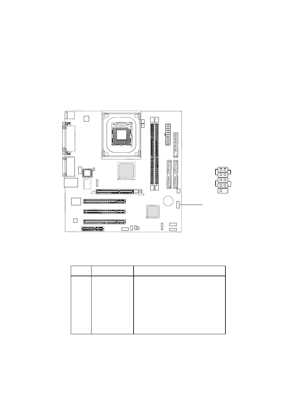
Front Panel Connector: JFP1
The mainboard provides one front panel connector for establishing elec-
trical connection to the front panel switches and LEDs. JFP1 is compliant with
Intel
®
Front Panel I/O Connectivity Design Guide.
JFP1
10
1
9
2
HDD
S
PWSW
RST
-
LED
P
+
+
-
-
+
PIN
SIGNAL
DESCRIPTION
1
HD_LED_P
Hard disk LED pull-up to +5V
2
FP PWR/SLP
MSG LED pull-up to +5V
3
HD_LED_N
Hard disk active LED
4
FP PWR/SLP
MSG LED pull-up to +5V
5
RST_SW_N
Reset Switch low reference pull-down to GND
6
PWR_SW_P
Power Switch high reference pull-up to +5V
7
RST_SW_P
Reset Switch high reference pull-up to +5V
8
PWR_SW_N
Power Switch low reference pull-down to GND
9
RSVD_DNU
Reserved. Do not use.
JFP1 Switch/LED Front Panel Electrical Connection
This manual is related to the following products: