Rs-485 port connection – Mace DVR1604RW User Manual
Page 59
DVR1604RW
Digital Video Recorder
Operational Manual
© 2004 Mace Security Products.
59
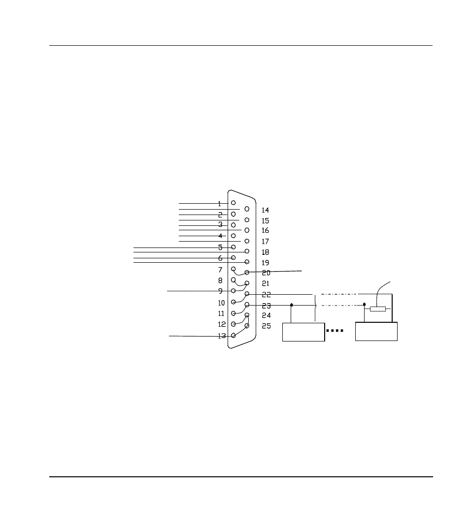
4. RS-485 port connection
If you want to control Camera pan-tilt-zoom (P/T/Z) or activate the DVR Output relay, the 25-pin RS485
connection must be used. See detail below.
The RS485 port connection can control various (P/T/Z) Cameras, and the specific model or protocol can be
selected from the Control Menu in System settings.
The DB25 pin outs are marked below. The definition of the pin outs are as follows: The broken line in the
graph indicates inside connection
a)
Pins 1,14,2,15,3,16,4,17 connects to alarm input: ALARM1~ALARM8
b)
Pins 5 & 18 = OUTPUT Relay 1 - 6 & 19 = OUTPUT Relay 2 Each Relay (normally open):
c)
Pins 7&20 = OUTPUT 3 is a controllable +12V output.
d)
Pins 8, 9 & 21 are +12V power output, Use for Low current items only such as Relays and Alarm Devices.
e)
Pins 10 & 22 are the B line of RS485, Pins 11 & 23 are the A line of RS485;
f)
Pins 12, 13, 24 & 25 are Ground (Gnd).
Combined as RS485 B line
Combined as RS485 A line
Decoder
Decoder
A B
A B
Alarm input ALARM 1
ALARM 8
Alarm output
ALARMOUT1
ALARMOUT2
Controllable +12V output
+12V output
Gnd
120
End of Line
(EOL)
resister
required .