Manual, Vport 351 panel layout – Moxa Technologies VPORT 351 User Manual
Page 4
- 4 -
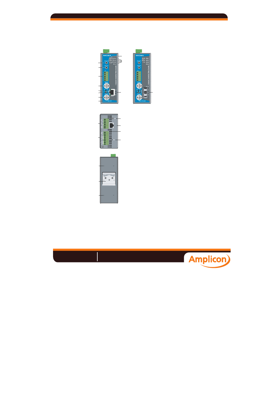
VPort 351 Panel Layout
VPort 351
Front Panel View
VPort 351-M-SC
Front Panel View
17
7
8
13
12
9
10
16
11
15
18
14
2
1
2
1
Top Panel View
Rear Panel View
20
19
19
V1, V2: 12-32 VDC
12-30 VAC
RS-232
CONSOLE
1
5
4
6
3
2
1. Grounding
screw
2. RS-232 console port
3. Hardware reset button
4. 6-pin terminal block for DI 1, DI 2,
power input 2 (PWR2)
5. 8-pin terminal block for Relay 1,
Relay 2, power input 1 (PWR1)
6. Heat dissipation orifices
7. LEDs for STAT, PWR1, PWR2,
FAULT
8. LEDs for VIDEO, AUDIO TEST, PTZ
9. AUDIO OUTPUT port for external
speaker
10. AUDIO INPUT port for mic-in and
line-in connection
11. 5-pin terminal block for RS-232/422/
485 connection
12. BNC port for video input
13. AUDIO TEST DIP switch for testing
audio input signal (default is off)
14. 75
Ω DIP switch for analog video
signal transmission with 75
Ω
resistance (default is on)
15. BNC port for loop-through video
output
16. RJ45 10/100BaseTX Ethernet Port
with 10 Mbps, 100 Mbps LEDs
17. 100BaseFX Fiber optic port with 100
Mbps LED
18. Model name
19. Screw hole for wall mounting kit
20. DIN-Rail mounting kit
Manual
Amplicon.co.uk
IT and Instrumentation for industry
Sales:
+44 (0) 1273 570 220
Website:
www.amplicon.co.uk
Email: