Manual, Ptz port, 100basefx ethernet port connection – Moxa Technologies VPORT 351 User Manual
Page 17
- 17 -
RJ45 (8-pin) to RJ45 (8-pin) Straight-Through Cable Wiring
Straight-Through Cable
RJ45 Plug Pin 1
Switch Port
RJ45
Connector
RJ45
Connector
Tx+
Tx-
Rx+
Rx-
VPort Ethernet
Port
Cable Wiring
3
3
6
6
1
1
2
2
Rx+
Rx-
Tx+
Tx-
RJ45 (8-pin) to RJ45 (8-pin) Cross-Over Cable Wiring
Cross-Over Cable
RJ45 Plug Pin 1
NIC Port
RJ45
Connector
RJ45
Connector
Tx+
Tx-
Rx+
Rx-
(Rx+)
(Rx-)
(Tx+)
(Tx-)
(Tx+)
(Tx-)
(Rx+)
(Rx-)
VPort Ethernet
Port
Cable Wiring
3
1
6
2
1
3
2
6
Rx+
Rx-
Tx+
Tx-
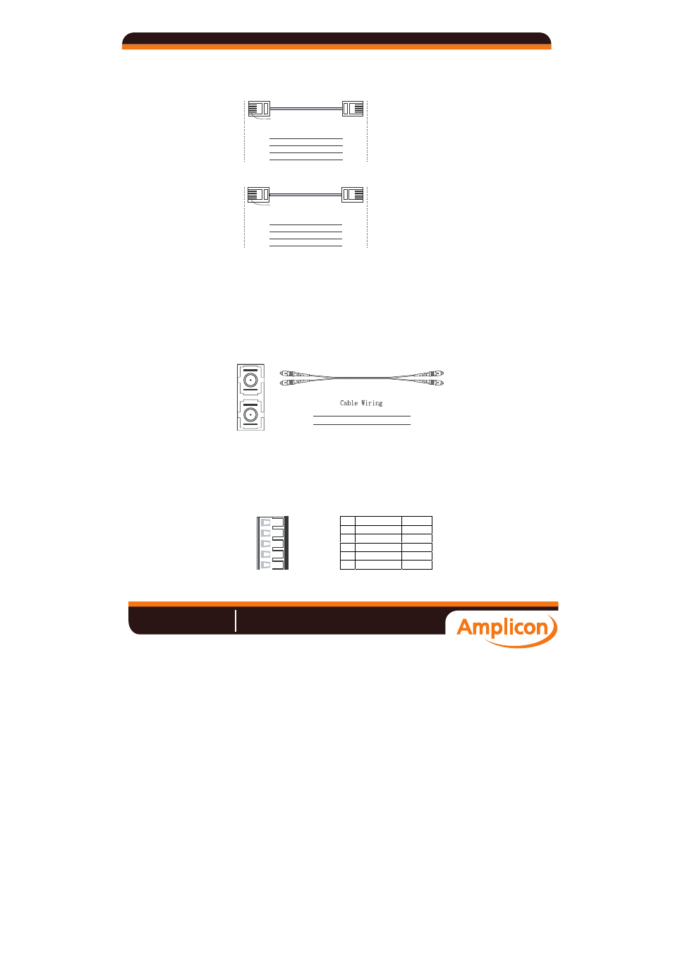
100BaseFX Ethernet Port Connection
The concept behind the SC port and cable is easy to understand. Since optical
signals do not require a circuit to transmit data, one cable is used to transmit
data and one cable is used to receive data, providing full-duplex transmission.
Remember to connect the Tx (transmit) port of device I to the Rx (receive) port
of device II, and the Rx (receive) port of device I to the Tx (transmit) port of
device II. If you make your own cable, we suggest labeling the two sides of the
same line with the same letter (A-to-A and B-to-B, as shown below, or
A1-to-A2 and B1-to-B2).
SC-Port Pinouts
SC-Port to SC-Port Cable Wiring
Tx
Rx
A
A
B
B
A
A
B
B
PTZ port
A PTZ port is located on the VPort 351’s front panel. The port is used to
connect to a PTZ motorized camera or device, so that the camera or device can
be controlled from the VPort over the IP network. The PTZ port supports
RS-232 or RS-422/485 signals through the terminal block. The PTZ port pin
assignments are shown in the following table.
Pin Assignment
1
3
2
4
5
PIN
RS-422/485
RS-232
1
GND GND
2
R- ---
3
R+
RxD
4
T-\D- ---
5
T+\D+ TxD
Manual
Amplicon.co.uk
IT and Instrumentation for industry
Sales:
+44 (0) 1273 570 220
Website:
www.amplicon.co.uk
Email: