Manual, Led indicators – Moxa Technologies VPORT 351 User Manual
Page 18
- 18 -
LED Indicators
Several LED indicators are located on the front panel of the VPort 351. The
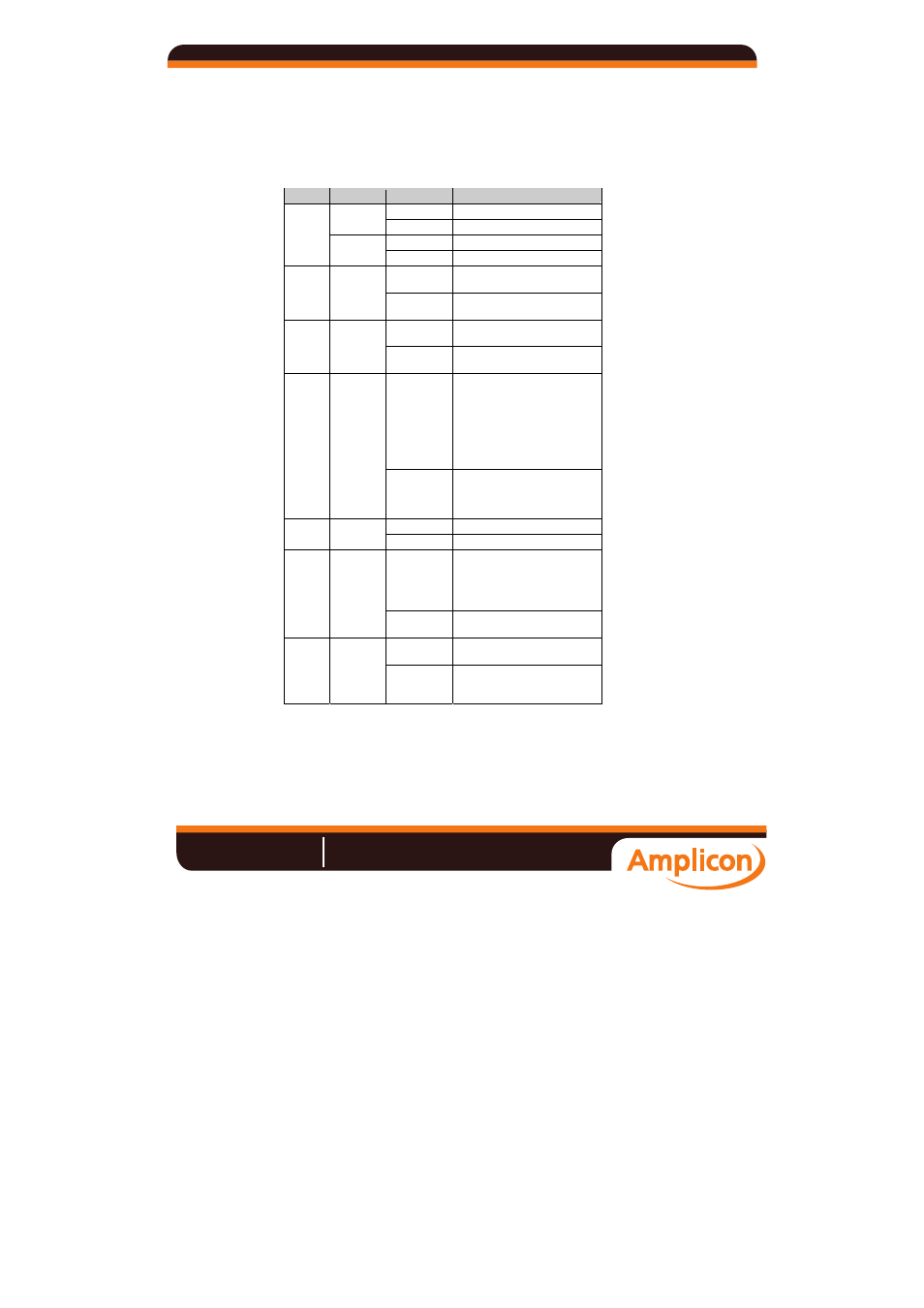
function of each LED is described in the table below.
LED
Color
State
Description
ON Hardware
initialization
RED
FLASH Software
initialization
ON System
boot-up
STAT
GREEN
FLASH
Firmware upgrade proceeding
On
Power is being supplied to power
input PWR1
PWR1
AMBER
Off
Power is not being supplied to
power input PWR1
On
Power is being supplied to power
input PWR2
PWR2
AMBER
Off
Power is not being supplied to
power input PWR2
On
Three conditions could cause the
LED to light up:
1. One of the 2 power inputs is
disconnected.
2. Video loss
3. Network disconnected Users can
modify the settings on the system
configuration system alarm page.
FAULT
RED
Off
Both power inputs are connected
and working, or there is no video
loss, or the network disconnected
alarm is silent (if it is activated).
On
Video signal is detected
VIDEO
GREEN
Off
Video signal is not detected
On
Audio input signal is looped-back
directly to the audio output phone
jack for audio installation test
(AUDIO TEST DIP switch on the
front panel must be switched to ON)
AUDIO
TEST
GREEN
Off
Playback the remote client audio to
audio output phone jack
On
RS-232 or RS-485 signals are being
transmitted
PTZ
GREEN
Off
RS-232 or RS-485 signals are not
being transmitted or have not been
detected
Manual
Amplicon.co.uk
IT and Instrumentation for industry
Sales:
+44 (0) 1273 570 220
Website:
www.amplicon.co.uk
Email: