Portable forced air heaters, Service procedures, Continued – Master Lock B150CEA User Manual
Page 10
10
104468
PORTABLE FORCED AIR HEATERS
R
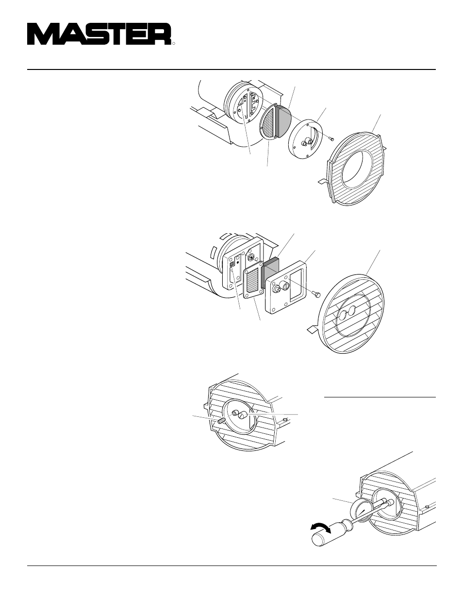
Air Output, Air Intake, and Lint
Filters
1.
Remove upper shell (see page 8).
2.
Remove filter end cover screws using
5/16" nut-driver.
3.
Remove filter end cover.
4.
Replace air output and lint filters.
5.
Wash or replace air intake filter (see
Preventative Maintenance Schedule,
page 6).
6.
Replace filter end cover.
7.
Replace fan guard and upper shell.
IMPORTANT: Do not oil filters
Pump Pressure Adjustment
1.
Remove pressure gauge plug from filter
end cover.
2.
Install accessory pressure gauge (part
number HA1180).
3.
Start heater (see Operation, page 5).
Allow motor to reach full speed.
4.
Adjust pressure. Turn relief valve to
right to increase pressure. Turn relief
valve to left to decrease pressure. See
specifications at right for correct pres-
sure for each model.
5.
Remove pressure gauge. Replace pres-
sure gauge plug in filter end cover.
Air Intake Filter
Lint Filter
Filter End
Cover
Air Output
Filter
Fan Guard
Figure 16 - Air Output, Air Intake, and Lint Filters, 35/70,000 Btu/Hr Models
Air Intake Filter
Filter End
Cover
Lint Filter
Air Output
Filter
Figure 17 - Air Output, Air Intake, and Lint Filters, 100/150,000 Btu/Hr Models
Figure 18 - Pressure Gauge Plug Removal
Pressure
Gauge
Plug
Pressure
Gauge
Model
Pump Pressure
(PSI/Bar)
35,000 Btu/Hr
2.9/0.20
70,000 Btu/Hr
3.8/0.26
100,000 Btu/Hr
3.9/0.27
150,000 Btu/Hr
4.8/0.33
(35/70,000 Btu/Hr Models Shown)
Relief
Valve
Fan Guard
SERVICE
PROCEDURES
Continued
Figure 19 - Adjusting Pump Pressure