Dca-125usj — output terminal panel connections – Multiquip MQ Power 60 Hz Generator DCA125USJ User Manual
Page 31
DCA-125USJ — OPERATION AND PARTS MANUAL — REV. #2 (01/27/11) — PAGE 31
1
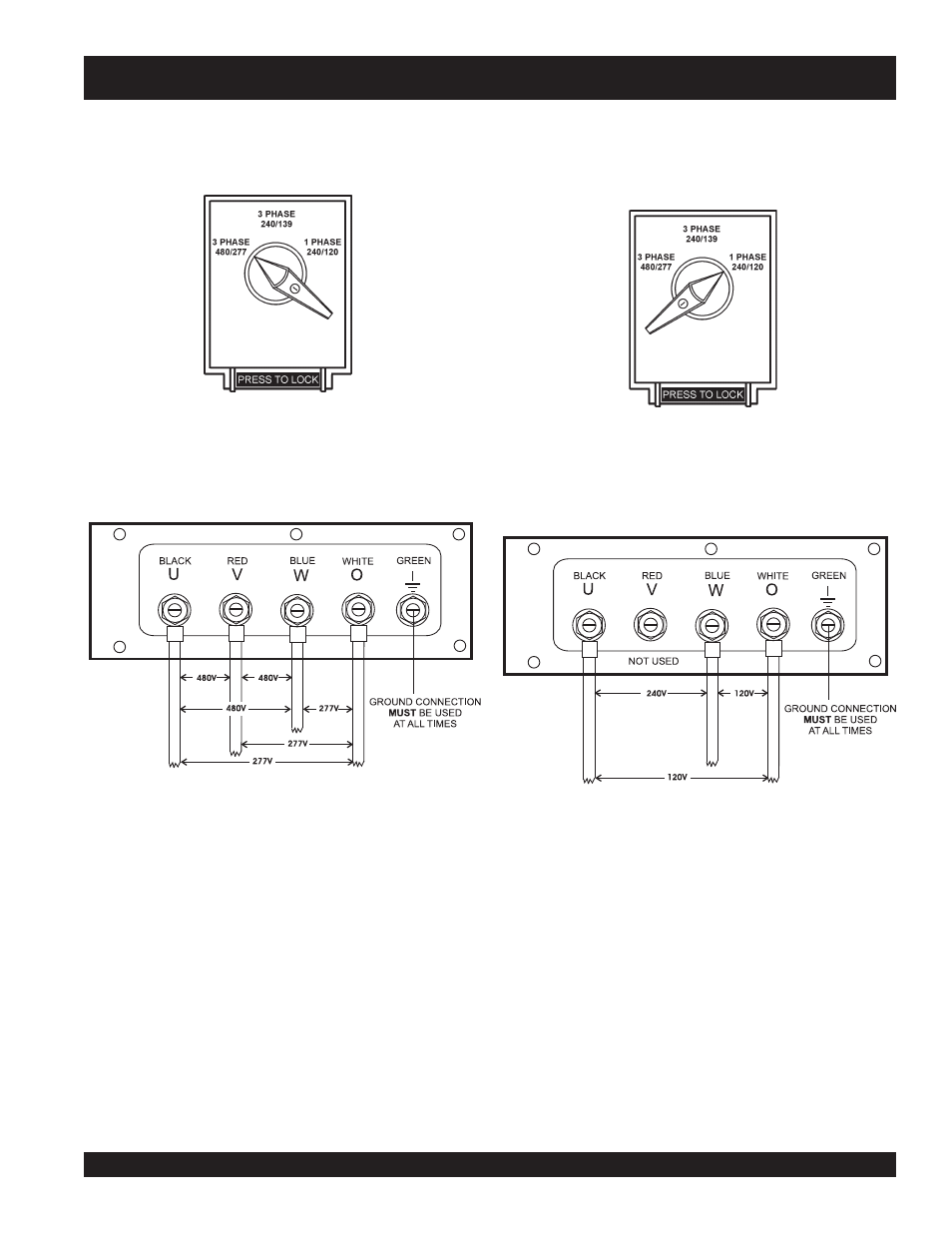
Figure 27. Voltage Selector Switch 480/277V
Three-Phase Position
3Ø 480/277 Output Terminal Lug Voltages
1. Place the voltage selector switch in the 3Ø 480/277
position as shown in Figure 27.
Figure 28. UVWO Terminal Lugs
480/277V Three Phase Connections
2. Connect the load wires to the
Output Terminal Lugs as
shown in Figure 28.
3. Turn the voltage regulator knob (Figure 24) clockwise to
increase voltage output, turn counterclockwise to
decrease voltage output.
1Ø 240V/120V Output Terminal Lug Voltages
1. Place the voltage selector switch in the 1Ø 240/120
position as shown in Figure 29.
2. Connect the load wires to the
Output Terminal Lugs as
shown in Figure 30.
3. Turn the voltage regulator knob (Figure 24) clockwise to
increase voltage output, turn counterclockwise to
decrease voltage output.
Figure 30. UVWO Terminal Lugs
1Ø-240V/120V Connections
DCA-125USJ — OUTPUT TERMINAL PANEL CONNECTIONS
Figure 29. Voltage Selector Switch 240/120V
Single-Phase Position