Stereo audio system, A/v receiver, Part ii: installation – MITSUBISHI ELECTRIC WS-65908 User Manual
Page 18: Figure 1) 1, Figure 2) 1
18
18
Y
G
Pb
B
Pr
R
V
H
HIGH RESOLUTION INPUT
INPUT
3
PIP
S-VIDEO
VGA
640X480, 60HZ
COMPONENT 480i /480p
1 (YPrPb)
2 (YPrPb)
DTV
(YPrPb/GRBHV)
480i /480p /1080i
VIDEO
MONITOR
IR EMITTER HOME THEATER
2
1
STB
OUTPUT
AUDIO-
LEFT/
(MONO)
AUDIO-
RIGHT
AUDIO-
LEFT/
(MONO)
AUDIO-
RIGHT
ANT-B
LOOP OUT
ANT-A
AV Receiver (M-VR900)
Back panel section
Attach
only
one
cable
type
1
1
2
3
White
Red
W
h
i
t
e
White
R
e
d
Red
TV back panel
Y
G
Pb
B
Pr
R
V
H
HIGH RESOLUTION INPUT
INPUT
3
PIP
S-VIDEO
VGA
640X480, 60HZ
COMPONENT 480i /480p
1 (YPrPb)
2 (YPrPb)
DTV
(YPrPb/GRBHV)
480i /480p /1080i
VIDEO
MONITOR
IR EMITTER HOME THEATER
2
1
STB
OUTPUT
AUDIO-
LEFT/
(MONO)
AUDIO-
RIGHT
AUDIO-
LEFT/
(MONO)
AUDIO-
RIGHT
ANT-B
LOOP OUT
ANT-A
Red
Red
Audio system back panel section
OUT
OUT
OUT
IN
IN
IN
IN
SUBWOOFER
(MONO)
CD
AUX
TAPE
1
TAPE
2
L
R
TV back panel
White
White
1
Please see your A/V receiver Owner’s
Guide for more detailed connections.
Additional connection cables are not
provided with the TV. They should be
available at most electronic stores.
Part II: Installation
C
o
nn
e
c
ti
n
g a
n A
u
d
io R
e
c
e
iv
e
r
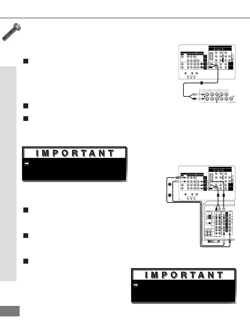
Connecting an Audio Receiver
Stereo Audio System
(Figure 1)
1
Connect the audio cables from AUDIO
MONITOR OUTPUT on the TV back
panel to TV IN or AUX IN terminals on
the back of the audio system. The red
cable connects to the R (right) channel,
and the white cable connects to the L
(left) channel.
2
Turn off the TV’s speakers through the
Audio/Video Menu, page 43.
3
Set the audio system’s input to the TV
or AUX position to hear the TV’s audio
through your stereo system.
A/V Receiver
(Figure 2)
1
Connect a video cable or S-Video
cable from VIDEO MONITOR OUT on
the back of the A/V receiver to VIDEO
INPUT-1 on the TV back panel.
2
Connect a video cable from VIDEO
MONITOR OUTPUT on the TV back
panel to VIDEO TV IN on the back of
the A/V receiver.
3
Connect a set of audio cables from
AUDIO MONITOR OUTPUT on the TV
back panel to AUDIO TV IN on the back
of the A/V receiver. The red cable con-
nects to the R (right) channel, and the
white cable connects to the L (left) chan-
nel.
Figure 1. Connecting the Stereo Audio System
Figure 2. Connecting the A/V Receiver.