Stb (set-top-box), Inputs 1-3, Output (monitor and pip) – MITSUBISHI ELECTRIC WS-65908 User Manual
Page 13: Antenna (ant-a, loop out, and ant-b), Component inputs 1-2, Dtv input
13
13
Y
G
Pb
B
Pr
R
V
H
HIGH RESOLUTION INPUT
INPUT
3
PIP
S-VIDEO
VGA
640X480, 60HZ
COMPONENT
480i / 480p
1 (YPrPb)
2 (YPrPb)
DTV
(YPrPb/GRBHV)
480i /480p /1080i
VIDEO
MONITOR
IR EMITTER HOME THEATER
2
1
STB
OUTPUT
AUDIO-
LEFT/
(MONO)
AUDIO-
RIGHT
AUDIO-
LEFT/
(MONO)
AUDIO-
RIGHT
ANT-B
LOOP OUT
ANT-A
1
2
3
4
5
6
7
8
Part II: Installation
B
a
c
k
P
a
n
e
l
F
u
nc
tio
n
s
Back Panel
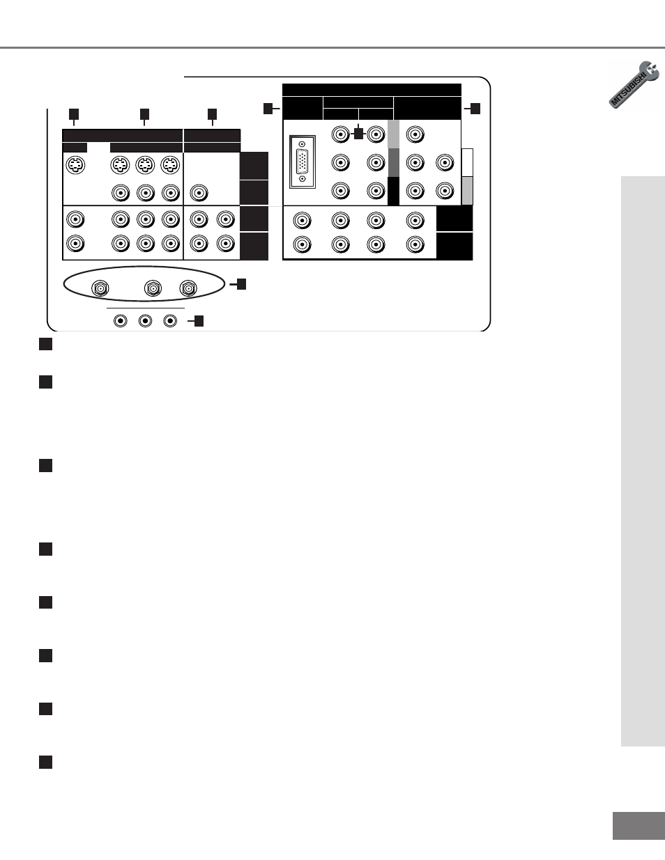
1
STB (Set-Top-Box)
This input can be used for the connection of any device with an S-Video output.
2
Inputs 1-3
These inputs can be used for the connection of a VCR, Super VHS (S-VHS) VCR, laser
disc player, or other A/V device to the TV. Please note that if you connect to the S-VIDEO
terminal, the VIDEO terminal is deactivated. The VIDEO terminal is active when there is
no S-Video connection.
3
Output (Monitor and PIP)
The Monitor Output sends the TV audio and video signals, excluding component video,
VGA, or DTV video, to an A/V receiver or other equipment. The PIP output sends the
PIP’s or POP’s audio signal to an ampli er or wi rel ess headphones. If no PI P or POP is
displayed, the PIP output will send the main picture audio signal.
4
Antenna (ANT-A, LOOP OUT, and ANT-B)
ANT-A and ANT-B receive signals from VHF/UHF antennas or a cable system. LOOP OUT
sends the ANT-A signal out to another component, such as a cable box or VCR.
5
IR Emitter Home Theater (System 4 Home Theater IR Control)
Connecting IR emitters here allow the TV to automatically change a digital A/V receiver’s
input in a home theater setup, and pass IR commands to other A/V devices.
6
VGA
This input can be used for the connection of a computer. Please see Appendix B, page
61, for signal compatibility.
7
Component Inputs 1-2
These inputs can be used for the connection of A/V equipment with component video
outputs, such as a DVD player. Please see Appendix B, page 61, for signal compatibility.
8
DTV Input
This input is used to connect a DTV receiver, and can be con gur ed f or HDTV c omp onent ,
RGB sync on green, and RGB plus H&V. Please see Appendix B, page 61, for signal
compatibility.