Installation – Grandstream Networks Grandstream GXP-1200 User Manual
Page 5
Grandstream Networks, Inc.
GXP User Manual
Page 5 of 39
Firmware 1.1.6.46
Last Updated: 03/2008
Installation
E
QUIPMENT
P
ACKAGING
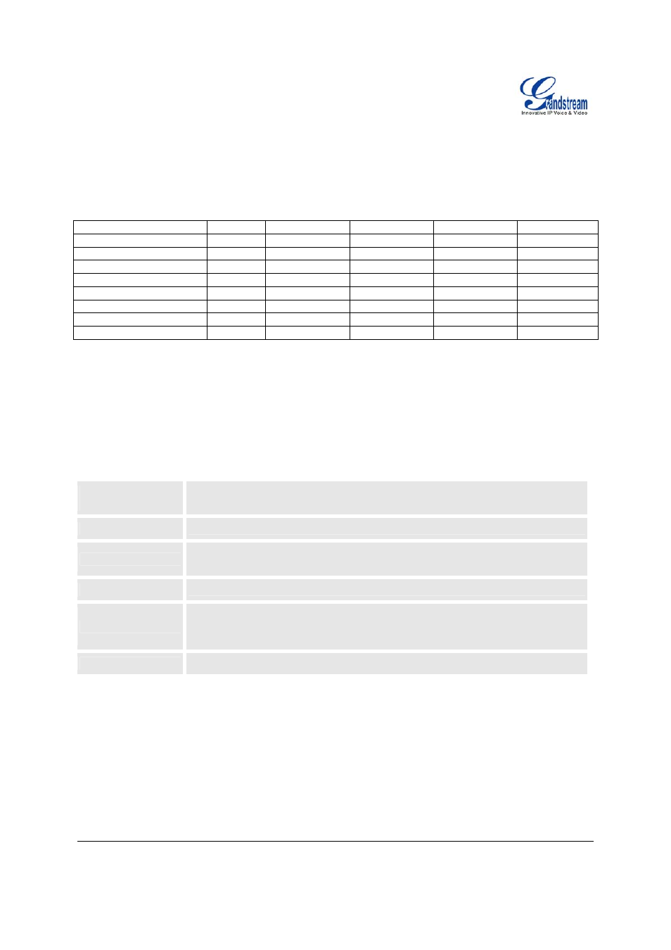
Table 1: Equipment Packaging
GXP-280
GXP-1200 GXP-2000 GXP-2010 GXP-2020
Main Case
Yes
Yes Yes Yes Yes
Handset
Yes
Yes Yes Yes Yes
Phone Cord
Yes
Yes Yes Yes Yes
Power Adaptor
Yes
Yes Yes Yes Yes
Ethernet Cable
Yes
Yes Yes Yes Yes
High Phone Stand
No
Yes No Yes Yes
Low Phone Stand
Yes No
No
Yes Yes
Wall Mount Spacers (2)
No
Yes No Yes Yes
C
ONNECTING
Y
OUR
P
HONE
The connectors of the GXP1200/2010/2020 are located on the bottom of the device while they are located on
the back side of the GXP280/2000.
Table 2: GXP Connectors
EXT
Connects the GXP Extension unit directly to the GXP using connection cable.
Draws power from PoE if provided by network.
PC
10/100Mbps RJ-45 ports for PC (downlink) connection.
LAN
10/100Mbps RJ-45 port for LAN (uplink) connection. Supports PoE (802.3af).
Draws power from either spare line or signal line.
Power Jack
5V DC power port; UL Certified
Headset Jack
RJ22 and 2.5mm for GXP-280/2010/2020
RJ22 for GXP-1200
2.5mm for GXP-2000 HW Rev1.0 or later
Handset Jack
RJ11
GXP-2000
E
XTENSION
U
NIT
GXP–2000 supports two (2) extension units, providing up to 112 additional programmable extensions. Each
GXP Extension unit has 56 multi–purpose keys, dual color LEDs (red/green) and support BLF (Busy Lamp
Field) and Presence.
GXP–2000 Extension package contains: