7) f_usb1/f_usb2/f_usb3 (usb headers) – GIGABYTE GA-M68MT-S2P User Manual
Page 16
Hardware Installation
- 16 -
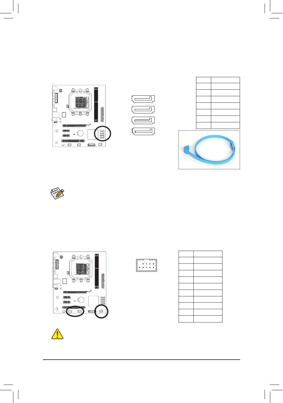
6) SATA2_0/1/2/3 (SATA 3Gb/s Connectors)
The SATA connectors conform to SATA 3Gb/s standard and are compatible with SATA 1.5Gb/s standard.
Each SATA connector supports a single SATA device. The NVIDIA
®
GeForce 7025/nForce 630a chipset
supports RAID 0, RAID 1, RAID 5, RAID 10, and JBOD. Refer to
Chapter 4, "Configuring SATA Hard
Drive(s)," for instructions on configuring a RAID array.
Pin No. Definition
1
GND
2
TXP
3
TXN
4
GND
5
RXN
6
RXP
7
GND
• A RAID 0 or RAID 1 configuration requires at least two hard drives. If more than two hard
drives are to be used, the total number of hard drives must be an even number.
• A RAID 5 configuration requires at least three hard drives. (The total number of hard drives
does not have to be an even number.)
• A RAID 10 configuration requires four hard drives.
DEBUG
PORT
G.QBOFM
7
1
SATA2_3
SATA2_2
DEBUG
PORT
G.QBOFM
7
1
SATA2_1
DEBUG
PORT
G.QBOFM
7
1
SATA2_0
DEBUG
PORT
G.QBOFM
7
1
Please connect the L-shaped end of
the SATA cable to your SATA hard
drive.
7) F_USB1/F_USB2/F_USB3 (USB Headers)
The headers conform to USB 2.0/1.1 specification. Each USB header can provide two USB ports via an
optional USB bracket. For purchasing the optional USB bracket, please contact the local dealer.
Pin No. Definition
1
Power (5V)
2
Power (5V)
3
USB DX-
4
USB DY-
5
USB DX+
6
USB DY+
7
GND
8
GND
9
No Pin
10
NC
DEBUG
PORT
G.QBOFM
10
9
2
1
• Do not plug the IEEE 1394 bracket (2x5-pin) cable into the USB 2.0/1.1 header.
• Prior to installing the USB bracket, be sure to turn off your computer and unplug the power
cord from the power outlet to prevent damage to the USB bracket.