Installation, Install ductwork, Concrete slab – Greenheck Fan VSU Make-Up Air Unit with Direct-Fired Gas Heater 470654 User Manual
Page 7: Service and access clearance, Clearance to combustibles
7
Model VSU Make-Up Air
®
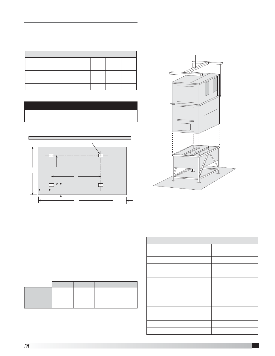
Burner/Blower Section
Use a crane and a spreader bar hooked to the factory
lifting lugs (shown below)
to lift and center the unit onto
the filter stand section. The sections should be caulked
together.
Install Ductwork
This table shows the duct sizes and straight lengths
recommended for optimal performance (AMCA
Publication 201-90). Using duct sizes less than
recommended will affect fan performance. Good
duct installation practices should be followed for the
remaining ductwork.
Recommended Supply Ductwork Sizes
VSU
Blower Size
Duct Size
(in.)
Straight Duct Length
(in.)
108
10x13
32
109
14x13
38
110
16x14
42
112
18x16
48
115
19x16
49
118
24x22
64
120
28x28
79
218
68x24
114
220
68x26
118
225
104x37
175
230
104x37
203
Installation
Concrete Slab Dimensions
Housing Size
A
B
C
D
E
20
64
64
42
37
37
30
77
76
42
49
49
40
78
135
42
51
108
50
87
180
42
60
153
All dimensions are shown in inches.
Building Wall
A
B
C
Concrete Slab
Approx. Stand Feet Locations
Requir
ed with service
platform only
12
E
D
12
Unit Contr
ol Side
Concrete Slab and Unit Footprint
Concrete Slab
The first step in unit installation is to pour a concrete
slab capable of holding the unit weight as a base. The
slab should have a proper gravel drainage bed.
Service and Access Clearance
The slab should be positioned to allow 3 feet of
clearance on the control end of the unit and 2 feet of
clearance on the other three sides. Housing size 50
requires 3 feet of clearance on both ends because of
filters access. Note that the concrete forms a 1 foot
wide apron on all four sides of the unit unless a 42 in.
extension is added to the control end of the unit.
NOTE
If optional service platform is included, a minimum of
42 inches must be added to Dimension B.
Clearance to Combustibles
Floor
Top
Sides
Ends
Insulated/
Units
0 in.
(0 mm)
0 in.
(0 mm)
0 in.
(0 mm)
0 in.
(0 mm)
Non Insulated
Units
0 in.
(0 mm)
6 in.
(152.4 mm)
6 in.
(152.4 mm)
6 in.
(152.4 mm)
Clearance to combustibles is defined as the minimum distance required
between the heater and adjacent combustible surfaces to ensure the
adjacent surface’s temperature does not exceed 90 degrees above the
ambient temperature.
Spreader Bar