Installation instructions, Installation, Safety precautions – Stovax Brunel 8050 User Manual
Page 10: Installation of the stove
10
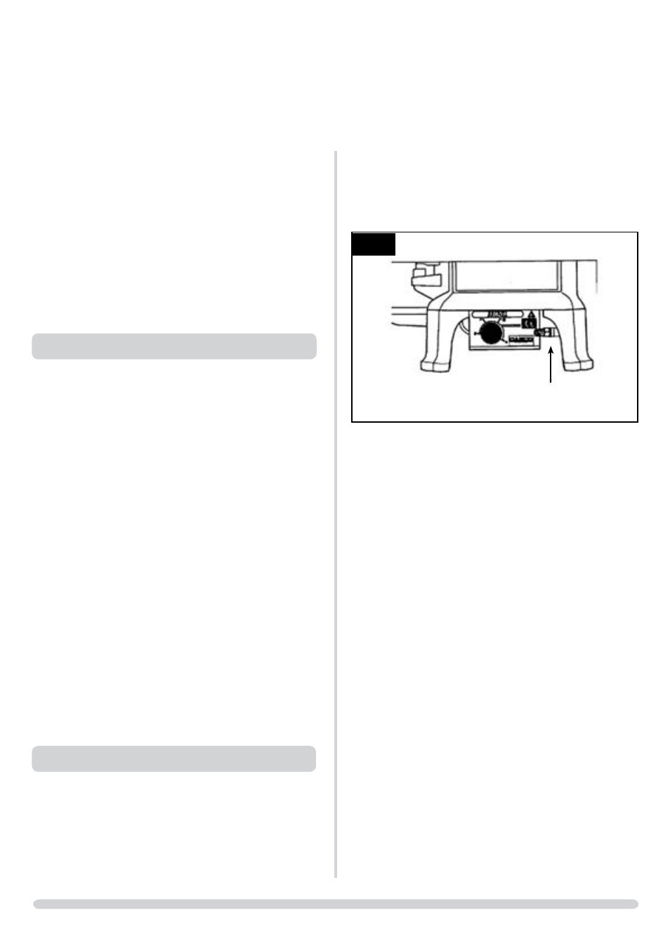
2.3 Having run the gas supply to the stove, PURGE THE
SUPPLY PIPE, this is essential to expel any debris that may
block the gas controls.
• Connect the gas supply to the 8mm-compression elbow
at the RH rear corner of the stove, Diagram 3.
AR0396
3
2.4 • Check the pull of the flue system by applying a lighted
smoke pellet to the flue system opening.
If there is a definite flow into the chimney, proceed with
the installation, if not warm the chimney for a few minutes.
IF THERE IS STILL NO DEFINITE FLOW, THE FLUE MAY
REQUIRE ATTENTION - SEEk EXPERT ADVICE
2.5 The flue system may now be connected to the stove:
• Ensure that all joints are sealed with a suitable fire
resistant sealant.
It is also recommended that a physical retention method be
used at the flue spigot joint, self-tapping screws being
favoured.
2.6 • Connect a suitable pressure gauge to the test point
located on the inlet fitting,
• Turn the gas supply on
• Light the appliance and check all gas joints for possible
leaks
• Turn the appliance to a maximum and check that the
supply pressure is as stated on the databadge.
• Turn the gas off and replace the test point screw
• Turn the gas on and check the test point for leaks.
NOTE: The stove is also suitable for installation onto a
fireplace opening. The following method illustrates how this
can be achieved with the aid of the optional closure plate
and spigot extension:
• Ensure that the fireplace dimensions are shown in
Diagram 4.
IMPORTANT: ENSURE THAT THE APPLIANCE IS
CORRECTLY ADJUSTED FOR THE GAS TYPE AND
CATEGORY APPLICABLE IN THE COUNTRY OF USE.
REFER TO DATABADGE AND TECHNICAL
SPECIFICATIONS AT THE FRONT OF THE BOOkLET.
LPG MODELS: THE APPLIANCE IS FACTORY SET TO
RUN ON BUTANE G30. IF IT IS INTENDED TO BE USED
ON PROPANE G31 THE AERATION PLATE SUPPLIED
MUST BE FITTED.
FOR DETAILS OF CHANGING AERATION PLATES REFER
TO SECTION 29.
FOR DETAILS OF CHANGING BETWEEN GAS TYPES
REFER TO SECTION 30.
1. SAFETY PRECAUTIONS
1.1 This appliance must be installed in accordance with the
rules in force, and used only in a sufficiently ventilated
space. Place read these instructions before installation and
use of this appliance.
1.2 All the instructions must be left intact with the user.
1.3 In your own interest, and those of safety, this appliance
must be installed by a competent person in accordance
with local and national codes of practice. Failure to install
the appliance correctly could lead to prosecution.
1.4 This appliance is intended for use on a governed gas
installation and set to the required pressure.
1.5 Keep all plastic bags away from young children.
1.6 Do not place any object on or near to the stove. Allow
adequate clearance above the stove, see Technical
Specification.
1.7 The stove is fitted with the Gazco Flue Sure System, which
will act to cut off the gas supply to the appliance in the
event of incorrect operation of the flue. If the system acts to
shut off the gas supply, this indicates that there is insufficient
flue pull. If this occurs a minimum of 10 minutes should be
allowed before trying to relight. Continued operation of this
safety device means that there may be a serious problem
with the flue system; a qualified gas engineer should inspect
this. DO NOT USE THE STOVE UNTIL AN ENGINEER
SAYS IT IS SAFE TO DO SO.
1.8 The Flue Sure System must not be tampered with. Use only
genuine Gazco replacement parts when servicing the system
- refer to servicing section on page 15.
2. INSTALLATION OF THE STOVE
2.1 • Remove the outer carton
• Take the stove off the pallet and remove the accessory
carton.
2.2 • Position the stove ensuring all appropriate clearances are
observed.
INSTALLATION INSTRUCTIONS
INSTALLATION