English – GIGABYTE GA-7vkml User Manual
Page 30
- 26 -
GA-7VKML Series Motherboard
English
20 ) F_PANEL (2x7 pins connector)
HD (IDE Hard Disk Active LED)
Pin 1: LED anode(+)
Pin 2: LED cathode(-)
SPK (S peaker Connector)
Pin 1: VCC(+)
Pin 2- Pin 3: NC
Pin 4: Data(-)
RST (Reset Sw itch)
Open: Normal Operation
Close: Reset H ardware System
PD+/PD_G-/PD_Y-(Power LED)
Pin 1: LED anode(+)
Pin 2: LED cathode(-)
Pin 3: LED cathode(-)
PW (Soft Power Connector)
Open: Normal Operation
Close: Power On/Off
Ø Please connect the power LED, PC speaker, reset switch and power switch etc of your chassis
front panel to the F_PANEL connector according to the pin assignment above.
1
2
13
14
HD-
HD+
PD_Y-
PD_G-
PD+
PW- PW+
SPK-
SPK+ RST+
RST-
1
1
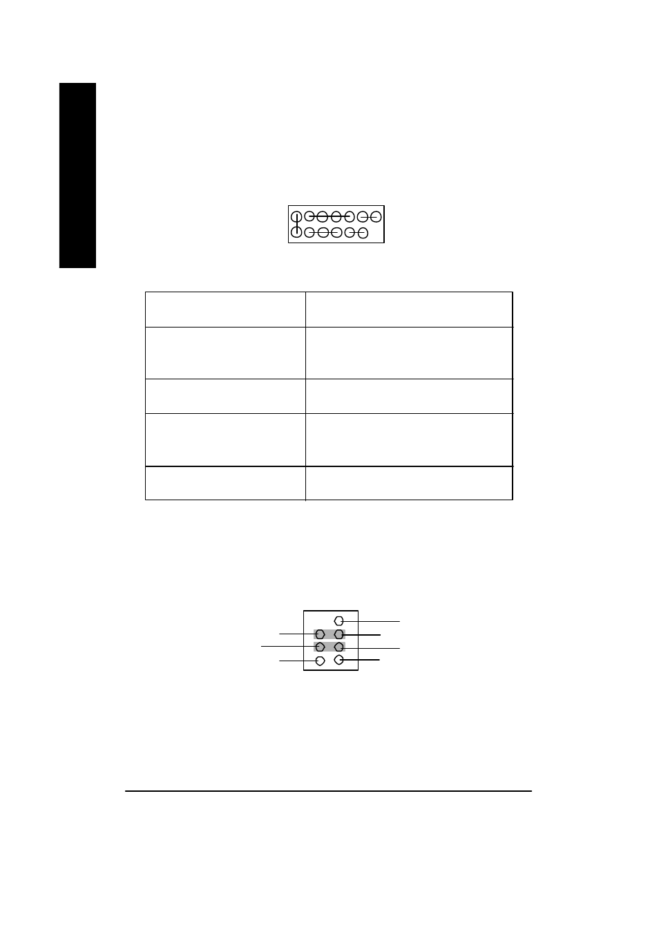
21 ) F_AUDIO (Front Audio)
Ø If you want to use "Front Audio" connector, you must remove 3-4, 5-6 Jumper. In order to utilize
the front audio header, your chassis must have front audio connector. Also please make sure
the pin assigment on the cable is the same as the pin assigment on the MB header. To find out
if the chassis you are buying support front audio connector, please contact your dealer.
2
1
8
7
MIC
Front Audio (R)
Front Audio (L)
GND
GND
Rear Audio (R)
Rear Audio (L)