Air flow adjustments, Psc m, Motor sheave adjustments v – Goodmans COMMERCIAL HEATING & COOLING 3 TON - 6 TON PACKAGE GAS UNIT CPG SERIES User Manual
Page 22: Maintenance
22
To connect manometer to gas valve:
1. Back outlet pressure test screw (inlet/outlet pressure
boss) out one turn (counterclockwise, not more than
one turn).
2. Attach a hose and manometer to the outlet pressure
boss of the valve.
To remove manometer from gas valve:
1. Remove manometer hose from outlet pressure boss.
2. Turn outlet pressure test screw in to seal pressure
port (clockwise, 7 in-lb. minimum).
3. Turn on electrical power and gas supply to the system.
4. Turn on system power and energize valve.
5. Using a leak detection solution or soap suds, check
for leaks at pressure boss screw. Bubbles forming
indicate a leak. SHUT OFF GAS AND FIX ALL LEAKS
IMMEDIATELY.
T
O
PREVENT
UNRELIABLE
OPERATION
OR
EQUIPMENT
DAMAGE
,
THE
GAS
MANIFOLD
PRESSURE
MUST
BE
AS
SPECIFIED
ON
THE
UNIT
RATING
PLATE
. O
NLY
MINOR
ADJUSTMENTS
SHOULD
BE
MADE
BY
ADJUSTING
THE
GAS
VALVE
PRESSURE
REGULATOR
.
CAUTION
AIR FLOW ADJUSTMENTS
The drive on the supply fan is typically set in the middle of the
RPM range. The drive motor sheave pitch diameter is field
adjustable for the required airflow. Refer to “Drive
Adjustments” section below.
When the final adjustments are complete, the current draw
of the motor should be checked and compared to the full
load current rating of the motor. The amperage must not ex-
ceed the service factor stamped on the motor nameplate.
The total airflow must not be less than that required for op-
eration of the electric heaters or the furnace.
If an economizer is installed, check the unit operating bal-
ance with the economizer at full outside air and at minimum
outside air. Upon completion of the air flow balancing, we
recommend replacing the variable pitched motor sheave with
a properly-sized fixed sheave. A matching fixed sheave will
provide longer belt and bearing life and vibration free opera-
tion. Initially, it is best to have a variable pitched motor sheave
for the purpose of airflow balancing, but once the balance
has been achieved, fixed sheaves maintain alignment and
minimize vibration more effectively. For direct drive units, move
fan speed wire.
NOTE: Never run CFM below 350 CFM per ton, evaporator
freezing or poor unit performance is possible.
PSC M
OTOR
Adjust the CFM for the unit by changing the speed tap of the
indoor blower motor at the heat or cool tap on the control
board connection with the one of the speed taps on “M1” or
“M2” (Black-High Speed, Blue-Medium Speed, Red-Low
Speed).
EEM Motor
Adjust the CFM for the unit by changing the position of the
low voltage leads on the motor terminal block. Green is for
Fan Only. Yellow is for Cooling and Heat Pump Heating. Re-
fer to Appendix A for blower performance at each speed tap.
NOTE: If more than one lead is energized simultaneously,
the motor will run at the higher speed.
MOTOR SHEAVE ADJUSTMENTS
V
L
, V
M
, & 2
VP
V
ARIABLE
P
ITCH
K
EY
T
YPE
M
OTOR
S
HEAVES
The driving and driven motor sheaves should be in align-
ment with each other and the shafts parallel.
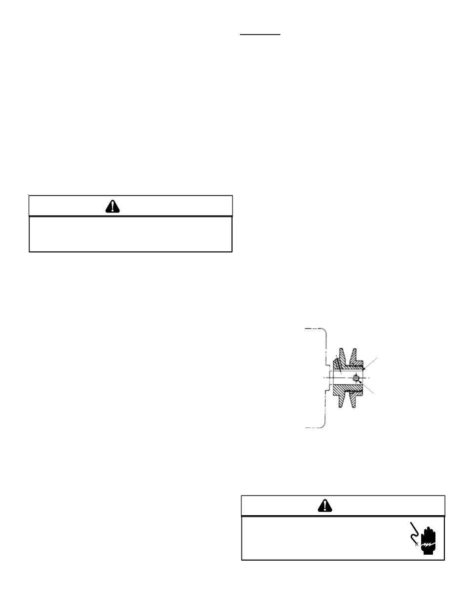
V
L
& V
M
S
HEAVES
A
DJUSTMENT
1. Loosen set screw “B” using a 5/32" Allen key.
2. Making half or full turns from closed position, adjust
sheave pitch diameter for desired speed. DO NOT
OPEN MORE THAN FIVE FULL TURNS.
3. Tighten set screw “B” securely over flat.
4. Carefully put on belts and adjust belt tension. DO NOT
FORCE BELTS OVER GROOVES.
5. Ensure all keys are in place and the set screws tight
before starting drive. Recheck set screws and belt
tension after 24 hours service.
NOTE: Future adjustments should be made by loosening the
belt tension and increasing or decreasing the pitch diameter
of the sheave by half or full turns as required. Readjust belt
tension before starting drive.
C
B
VL & VM
Sheave
NOTE: Do NOT operate sheave with flange projecting
beyond the hub end.
MAINTENANCE
HIGH VOLTAGE!
D
ISCONNECT
ALL
POWER
BEFORE
SERVICING
OR
INSTALLING
THIS
UNIT
. M
ULTIPLE
POWER
SOURCES
MAY
BE
PRESENT
. F
AILURE
TO
DO
SO
MAY
CAUSE
PROPERTY
DAMAGE
,
PERSONAL
INJURY
OR
DEATH
.
WARNING