Circulating air and filters d, Venting, Condensate drain connection c – Goodmans COMMERCIAL HEATING & COOLING 3 TON - 6 TON PACKAGE GAS UNIT CPG SERIES User Manual
Page 13: Warning, Caution
13
NOTE: The gas connection size at the unit does NOT
establish the size of the supply line.
3. These units are designed for either natural or propane
(LP) gas and are specifically constructed at the factory
for only one of these fuels. The fuels are NOT
interchangeable. However, the furnace can be
converted in the field from natural gas to LP gas with
the appropriate factory kit (see unit Technical Manual
for the appropriate kit). Only a qualified contractor,
experienced with natural and propane gas systems,
should attempt conversion. Kit instructions must be
followed closely to assure safe and reliable unit
operation.
4. With all units on a common line operating under full
fire, natural gas main supply pressure should be
adjusted to approximately 7.0" w.c., measured at the
unit gas valve. If the gas pressure at the unit is greater
than 10.5" w.c., the contractor must furnish and install
an external type positive shutoff service pressure
regulator. The unit will not function satisfactorily if
supply gas pressure is less than 5.5" w.c. or greater
than 10.5" w.c..
NOTE: A minimum horizontal distance of 48"
between the regulator and the furnace flue discharge
is required.
5. With all units on a common line operating under full
LP gas main supply pressure should be at least 11.0"
w.c. and must be no greater than 13.0" w.c., measured
at the unit gas valve. Unit will not function satisfactorily
if supply gas pressure is less than 11.0" w.c. or greater
than 13.0" w.c..
6. All pipe connections should be sealed with a pipe
thread compound, which is resistant to the fuel used
with the furnace. A soapy water solution should be
used to check all joints for leaks. A tap is located on
the entering side of the gas valve for test gauge
connection to measure supply (main) gas pressure.
Another tap is provided on the manifold side of the
gas valve for checking manifold pressure.
T
HIS
UNIT
AND
ITS
INDIVIDUAL
SHUTOFF
VALVE
MUST
BE
DISCONNECTED
FROM
THE
GAS
SUPPLY
SYSTEM
DURING
ANY
PRESSURE
TESTING
OF
THAT
SYSTEM
AT
TEST
PRESSURES
IN
EXCESS
OF
1/2 PSIG (13.8”
W
.
C
.).
WARNING
T
HIS
UNIT
MUST
BE
ISOLATED
FROM
THE
GAS
SUPPLY
PIPING
SYSTEM
BY
CLOSING
ITS
INDIVIDUAL
MANUAL
SHUTOFF
VALVE
DURING
ANY
PRESSURE
TESTING
EQUAL
TO
OR
LESS
THAN
1/2
PSIG.
CAUTION
7. There must be no obstruction to prevent the flow of
combustion and ventilating air. A vent stack is not
required and must never be used. The power venter
will supply an adequate amount of combustion air as
long as the air passageways are kept free of any
obstructions and the recommended external unit
clearances are maintained.
CIRCULATING AIR AND FILTERS
D
UCTWORK
The supply duct should be provided with an access panel
large enough to inspect the air chamber downstream of the
heat exchanger. A cover should be tightly attached to pre-
vent air leaks.
Ductwork dimensions are shown in the roof curb installation
manual.
If desired, supply and return duct connections to the unit may
be made with flexible connections to reduce possible unit
operating sound transmission.
VENTING
NOTE: Venting is self-contained.
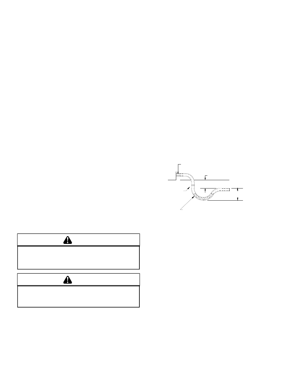
CONDENSATE DRAIN CONNECTION
C
ONDENSATE
D
RAIN
C
ONNECTION
A 3/4” NPT drain connection is supplied for condensate pip-
ing. An external trap must be installed for proper condensate
drainage.
DRAIN
CONNECTION
UNIT
2" MINIMUM
FLEXIBLE
TUBING-HOSE
OR PIPE
3" MINIMUM
A POSITIVE LIQUID
SEAL IS REQUIRED
Drain Connection
Install condensate drain trap as shown. Use 3/4" drain line
and fittings or larger. Do not operate without trap.
H
ORIZONTAL
D
RAIN
Drainage of condensate directly onto the roof may be ac-
ceptable; refer to local code. It is recommended that a small
drip pad of either stone, mortar, wood or metal be provided to
prevent any possible damage to the roof.
C
LEANING
Due to the fact that drain pans in any air conditioning unit
will have some moisture in them, algae and fungus will
grow due to airborne bacteria and spores. Periodic clean-
ing is necessary to prevent this build-up from plugging the
drain.