6 receiver systems – Grundig Digital Radio User Manual
Page 52
DIGITAL RADIO GUIDE
TERRESTRIAL TRANSMISSION SYSTEMS - HD RADIO
52
(3)
RF/Transmission System
“RF/Transmission” refers to channel coding and modulation. The channel coder
takes the multiplexed bit stream and applies coding and interleaving that can be
used by the receiver to reconstruct the data from the received signal, which
because of transmission impairments, may not accurately represent the transmitted
signal. The processed bit stream is modulated onto the OFDM subcarriers that are
transformed to time domain pulses, concatenated, and up-converted to the FM
band.
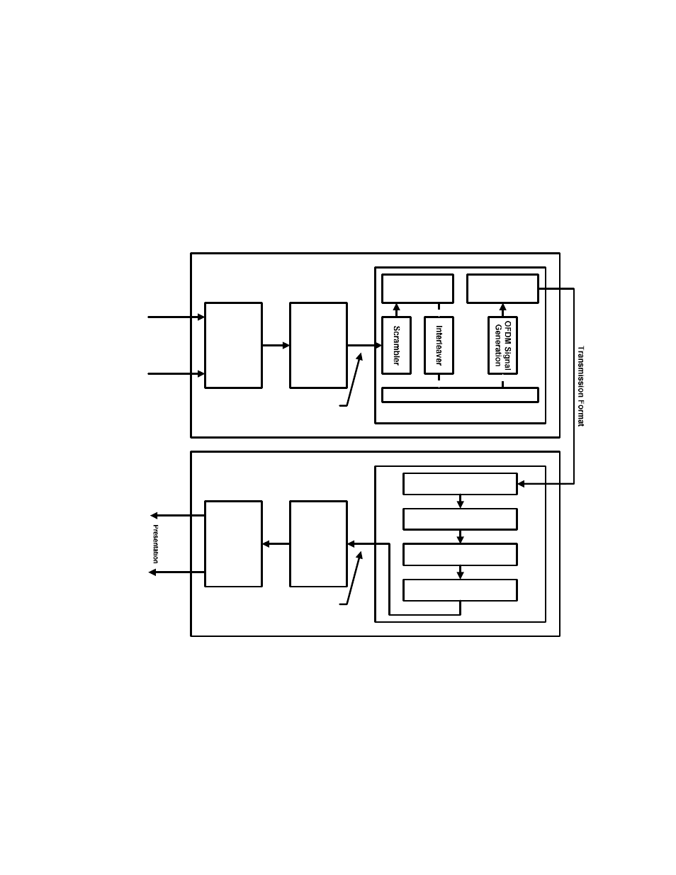
Figure 4.14: Block diagram of HD Radio transmission and reception multiplexing
7UDQVSRUW
DQG 0 XO
W
LSO
H[
$ SSO
LFDW
LRQ
( QFRGHUV
$ XGLR
' DW
D
7UDQVP LW
W
HU
XGLR
DW
D
5 HFHLYHU
$ SSO
LFDW
LRQ
' HFRGHUV
&KDQQHO
( QFRGLQJ
2 ) ' 0 6 XEFDUULHU 0 DSSLQJ
7UDQVIHU
) UDP HV
7UDQVP LVVLRQ
6 \ VW
HP
0 RGHP
7UDQVSRUW
DQG
' HP XO
W
LSO
H[
7UDQVIHU
) UDP HV
2 ) ' 0 ' HP RGXO
DW
RU
' HLQW
HUO
HDYHU
&KDQQHO
' HFRGHU
' HVFUDP EO
HU
0 RGHP
4.4.6
Receiver Systems
A functional block diagram of an HD Radio receiver is presented in Figure 4.15. The
signal is received by the antenna, passed through an RF front end, and mixed to an
intermediate frequency (IF), as in existing analogue receivers. Unlike typical analogue
receivers, however, the signal is then digitised at IF, and digitally down-converted to
produce in-phase and quadrature base band components. The hybrid signal is then
separated into an analogue component and a digital component. The analogue FM