Pentair/purex/minimax, Raypak rp2100 pool/spa heater, Sta-rite heater – Goldline LOGIC PL-P-4 User Manual
Page 19: Raypak rp2100, Sta-rite
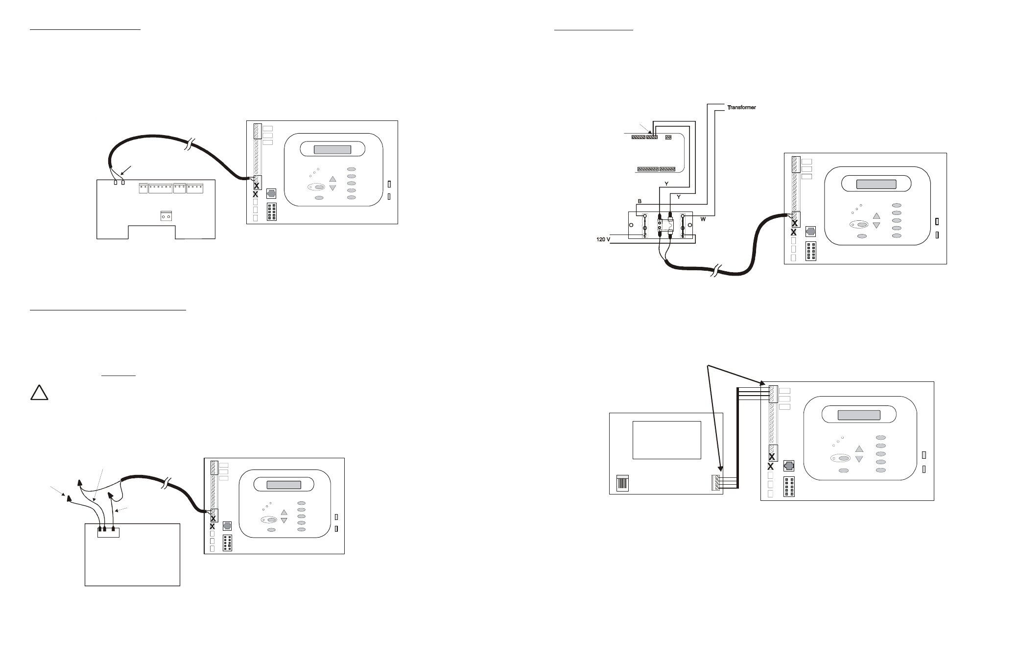
Pentair/Purex/MiniMax
1. Turn power off to heater.
2. Remove factory installed jumper from the “Ext Switch” connector.
3. Wire the Pro Logic to the “Ext Switch” connector as shown below.
4. The wires to the Pro Logic must be separated from any line voltage wires. Failure to follow these instructions
may cause erratic operation of the heater.
5. Set the Power (Thermostat Select) switch to either “Pool” or “Spa”.
6. Set the “Pool” and “Spa” thermostats to their maximum settings.
MINIMAX
Ext.
Switch
Remove
Factory Jumper
Raypak RP2100 Pool/Spa Heater
1. Turn power off to heater.
2. Push the mode button to “spa” mode.
3. Set the temperature to the maximum.
4. Push the mode button to “OFF”.
5. Lastly, plug the prewired connector in the P7 position on the board.
!
IMPORTANT: The heater will display “OFF” when it is being remotely controlled by the Pro Logic.
Some homeowners see the “OFF” display and, thinking this is a mistake, change the mode to “POOL” or
“SPA” which then disables the remote control by the Pro Logic. To prevent this: Remove the heater touch
pad connector (P5) which will disable the touchpad.
P7
Light Blue
Black
Orange Stripe
Orange
Stripe
Black
RAYPAK RP2100
Drawing is for digital
heater. If heater is a
millivolt (analog),
run red wires from
Fireman’s Switch
to heater relay.
15
STA-RITE Heater
1. Turn power off to heater.
2. Remove upper jacket and open the control box.
3. Remove the jumper for the “fireman’s switch.
4. Wire to the Pro Logic using wire rated for 105°C minimum.
STA-RITE
Terminal
Board
Operating
‘Control
Fireman’s
Switch
Hayward Variable Speed Filter Pump: Refer to the diagram below for proper low voltage communication wiring
between the Pro Logic and the Hayward Tristar Variable Speed Control (VSC).
4
2
3
1
GRN
YEL
BLK
RED
GRN
YEL
BLK
RED
VSC
Connect screw terminals
“1” to “1”, “2” to “2”, etc.
Use four conductor cable (typically phone cable) for communications connection between the VSC and the Pro Logic.
The maximum wiring distance is 500 feet (160 meters). Note that the terminals on both the VSC interface board and
the Pro Logic main board are numbered. The terminal connections should be matched between both terminal blocks
(connect 1 to 1, 2 to 2, etc.). The communications cable should be routed through the knockout hole on the left side
of the VSC enclosure, and a watertight fitting should be used to keep water and debris out of the opening. The
communications cable should also be routed away from the Pro Logic and VSC power connections if possible.
16