Grizzly G0654 User Manual
Page 23
Model G0654 (Mfg. Since 9/07)
-21-
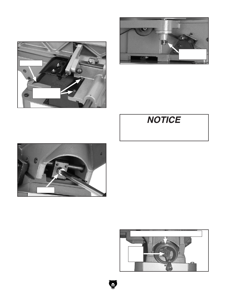
29. install the rear guard onto the carriage with
the two phillips head screws and flat wash-
ers already on the fence support, as shown
in
figure 28.
figure 28. rear guard installed on fence
support.
rear guard
phillips head
screws
30. thread the infeed table lever into the hole
shown in
figure 29, and tighten the m12-
1.75 lock nut.
figure 29. infeed lever installed.
31. move the fence back as far as possible.
32. remove the phillips head screw from the
forked end of the cutterhead guard shaft,
and slide the cutterhead guard shaft down
through the mounting hole on the table.
Note: The guard may not fully seat in the hole
initially; however, rotating the guard will allow
the shaft to fully seat in the hole.
33. thread the phillips head screw through the
forked end of the cutterhead guard shaft, as
shown in
figure 30.
34. rotate the guard one revolution counter-
clockwise as it appears from the top, then
hold the guard in position.
35. slide the fence forward and allow the guard
to swing back against the fence.
figure 30. phillips head screw installed on
cutterhead guard.
36. test the guard by pulling it back and letting it
go.
—the guard should snap back over the
cutterhead against the fence without drag-
ging across the table.
—if the guard drags across the table, loosen
the screw, raise the guard.
—if the guard does not snap back, remove it
and repeat
Steps 32–35.
37. attach the outfeed table adjustment handle
using the pre-installed phillips head screw
(see
figure 31).
figure 31. outfeed adjustment wheel.
lock nut
phillips head
screw
outfeed table adjustment handle
phillips
head
screw
The cutterhead guard must always return
to the closed position over the cutterhead
whenever it is moved.