Fig. 1 mounting the refreshment unit, Canopy frame installation, Canopy installation – Greenlee 28809-G01 User Manual
Page 18: Drain valve installation, Refreshment unit removal, Operation and service information
OPERATION AND SERVICE INFORMATION
Page 2
Owner’s Manual and Service Guide
Read all of manual to become thoroughly familiar with this vehicle. Pay particular attention to all Notes, Cautions and Warnings
CANOPY FRAME INSTALLATION
Orient the two canopy frame sections end to end aligning
five existing mounting holes as shown (Ref. Fig. 3 on
page 4) and fasten together with five 1/4 - 20 X 2" bolts
(item 26), ten 1/4" flat washers (item 27) and five 1/4 - 20
lock nuts (item 28). Orient the assembled canopy frame
as shown and rest front of frame on top mounting plate
and rear of frame on refreshment unit struts. Secure can-
opy frame to refreshment unit struts with two 1/4 - 20 X 1
1/4" bolts (item 29), four 1/4" flat washers (item 30) and
two 1/4 - 20 lock nuts (item 31) as shown. Secure canopy
frame to front strut with two 1/4 - 20 X 2" bolts (item 32),
four 1/4" flat washers (item 33) and two 1/4 - 20 lock nuts
(item 34) as shown. Tighten hardware firmly.
CANOPY INSTALLATION
Wipe canopy frame with a clean cloth. Unfold canopy
and locate clearance openings in the mounting flap.
Drape canopy over frame and orient canopy on frame so
that clearance openings match strut attachment points
and canopy frame juncture (Ref. Fig. 3 on page 4). With
the aid of assistants, pull canopy taut over canopy frame.
Fold mounting flap up inside canopy frame as shown.
Secure each mounting flap to inner surface of canopy
frame with #10 X 1/2" self tapping screws (item 35)
evenly spaced approximately 9" apart as shown. To pre-
vent “gathering” of canopy material during installation,
use the aid of assistants to hold the canopy taut while
securing to canopy frame. For best results, begin secur-
ing the canopy at the middle of each side and proceed to
each end of frame.
DRAIN VALVE INSTALLATION
Locate the drain hose ends and drain valve mounting
holes under the rear of unit. Orient each drain valve
assembly with spigot facing rearward. Attach each valve
assembly to unit with two 1/4 - 20 X 3/4" screws. Slide
the hose clamps onto the end of each drain hose. Push
the hose ends onto the drain valves and tighten clamps.
REFRESHMENT UNIT REMOVAL
T h e v e n d i n g u n i t i s
heavy. Care and proper
lifting equipment and
procedures must be used when removing unit to
reduce the possibility of severe injury and/or damage
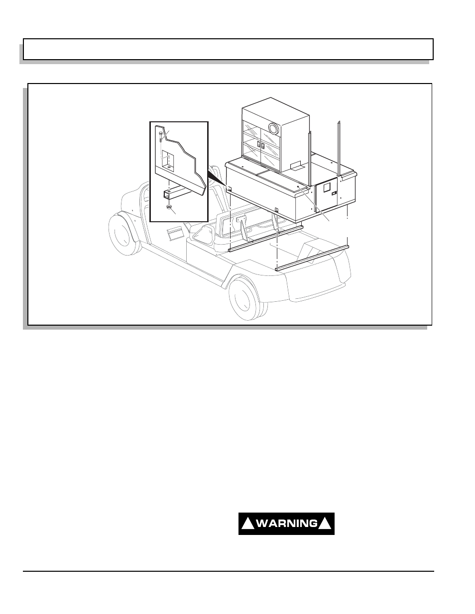
Fig. 1 Mounting the Refreshment Unit
1
2
Consumable Ice
(This Compartment Only)
Available Refreshment Unit
Accessories Include:
Sign Boards
Condiment Tray
Bottle Caddy
Mini Bottle Carrier
Humidor
Credit Card Machine Mount
Cash Drawer
Ref Rfi 1
!
!