1 general – Glow-worm EnergySaver 40 User Manual
Page 7
7
221834B
1 General
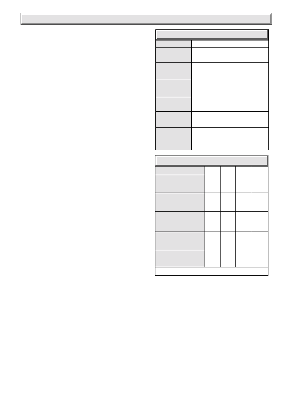
Rc
1
/
2
in.
GAS
CONNECTION
WATER
CONTENT
WATER
CONNECTION
28mm copper flow
at right return at left
LIFT
WEIGHT
240V ~ 50H
Z
, fused 3A.
ELECTRICITY
SUPPLY
1.6 Litre
(0.35 gal)
31.5 kg
(69.5 lb)
48.0 kg
(106 lb)
TOTAL
WEIGHT
40
DATA TABLE 1.
MODEL
RANGE RATING
NOMINAL
kW
HEAT INPUT
(GROSS)
Btu/h
NOMINAL
kW
HEAT
OUTPUT
Btu/h
10.16
10.16
11.86
13.55
34,680 34,680 40,462 46,240
8.79
8.79
10.26
11.72
30,000 30,000 35,000 40,000
9.40
9.40
10.97
12.53
32,100 32,100 37,400 42,800
NOMINAL
kW
HEAT
OUTPUT
Btu/h
CONDENSING
BURNER
m bar
SETTING (HOT)
PRESSURE in.w.g
9.7
9.7
12.7
16.6
3.88
3.88
5.1
6.64
0.96
0.96
1.1
1.3
34
34
39.9
45.5
APPROX
m
3
h
GAS
RATE
ft
3
h
LOW
MIN
MID
MAX
TABLE 2.
Energysaver 40
BURNER INJECTOR MARKING: 40N
1.5 Gas Supply
The gas installation must be in accordance with the current
issue of BS6891.
The supply from the governed meter must be of adequate size
to provide a steady inlet working pressure of 20mbar (8in wg) at
the boiler.
On completion, test the gas installation for soundness using the
pressure drop method and a suitable leak detection fluid, purge
in accordance with the above standard.
1.6 Electrical Supply
WARNING. This boiler must be earthed.
All system components shall be of the approved type and be
wired and connected in accordance with the requirements of
the current issue of BS7671 and any applicable local regulations.
Connection of the boiler and system controls to the mains
supply must be through a common isolator and must be fused
3A maximum. This method of connection should be, preferably,
by a double pole isolating switch, provided it has a minimum
contact separation of 3mm on both poles. This should be
readily accessible and preferably adjacent to the appliance. It
should supply the appliance only and be easily identifiable as so
doing.
Alternatively, an unswitched shuttered socket outlet and 3A
fused 3 pin plug both to the current issue of BS1363 may be
used, provided that they are not used in a room containing a
bath or shower.
Wiring to the boiler must be PVC insulated type to the current
issue of BS6500 Table 16.
1.7 Condensate
The boiler condensate should, if possible, be discharged into
the household internal draining system, that is, sink or washing
machine drain. If this is not practicable, discharge can be
external, into the household drainage system or a purpose
designed soakaway
The boiler is fitted with a safety device to prevent the boiler from
working if the condensate pipe gets blocked by either ice or
debris.
It is, therefore, recommended that any external condensate
drain pipe is insulated to prevent it freezing up.
Alternatively, a larger diameter pipe can be used and insulated.
The condensate drain pipe should be checked during any
servicing and any debris found removed.
Refer to the British Gas publication “Guidance Note for the
Installation of Domestic Condensing Boilers” for further
information.
1.8 Heating System Controls
The heating system should have installed: a programmer and
room thermostat controlling the boiler.
Thermostatic radiator valves may be installed in addition to the
room thermostat.
Note: For further information, see The Building Regulations
1991 - Conservation of fuel and power, 1995 edition - Appendix
G, table 4b.
1.9 Anti-theft Kits
Anti-theft kits are available for these appliances, contact
Hepworth Heating Ltd. for further information.