5 preparation – Glow-worm EnergySaver 40 User Manual
Page 14
14
221834B
Diagram 5.1
Diagram 5.2
Diagram 5.3
SECURING
SCREW(4)
INNER
FITTING
➁
M5x10mm
➀
SELF TAPPER
Note: Casing securing screws
supplied in loose items pack.
Fit in order of numerical sequence.
No.10 x
3
/
4
INNER
CASE
6289
6290
6288
5 Preparation
BASE TRAY
WALL
TEMPLATE
TOP
CARTON
WRAP
BOILER MOUNTING
BRACKET
INSTRUCTIONS
TOP FITTING
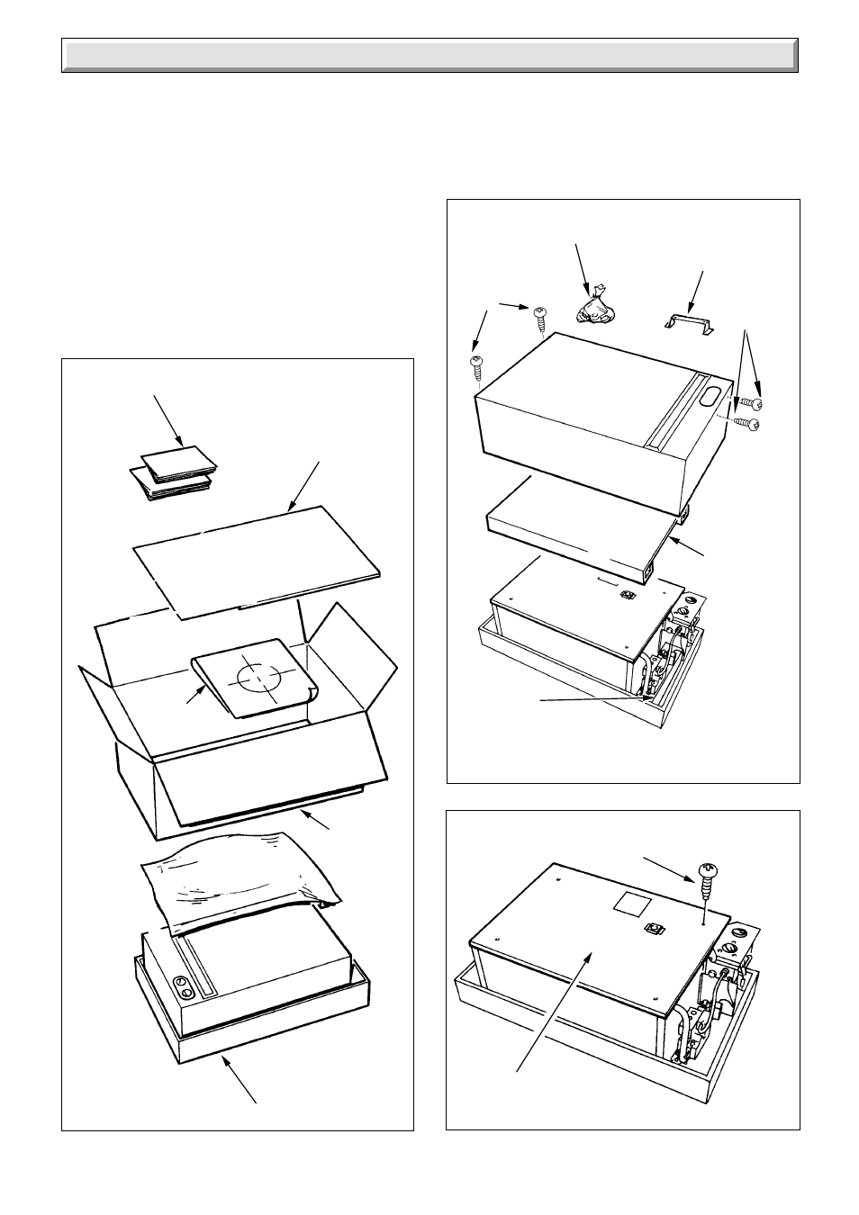
5.1 Unpacking: diagram 5.1
Open top carton, remove top fitting, wall template, loose items
fittings pack and boiler mounting bracket.
Remove carton wrap and spacing pieces
Lift off white outer case front. Remove protective packing piece.
Remove the cover of the inner case, see diagram 5.3.
5.2 Rear and Side Flue Application
Having selected the location and flue application, with due
regard to the terminal position:
Take the template and temporarily position it on the wall see
diagram 5.4, making sure that the minimum clearances are
maintained.
For a rear flue, mark the position of the flue as diagram 5.4.
LOOSE ITEMS PACK
CONTROLS
FITTING
For a side flue, extend the centre line horizontally (taking into
account the required fall towards the boiler) left or right to the
corner of the adjacent surface where the flue is required to exit
to the outside. Alternatively, the increase in the centre height
over a distance “X” is given by H = 0.35X. Mark the position of
the centre of the flue as in diagram 5.4.