12 servicing, 13 fault finding – Glow-worm EnergySaver 40 User Manual
Page 26
26
221834B
13.1 Electrical
Important. On completion of the Service/Fault Finding task
which has required the breaking and remaking of the electrical
connections the earth continuity, polarity, short circuit and
resistance to earth checks must be repeated using a suitable
multimeter.
Refer to Fault Finding, Wiring, diagram 13.2 and Functional
Flow diagram 13.3.
Note. Failure of an indicator light does not warrant the
replacement of an otherwise satisfactory part.
13.2 Electrical Supply Failure
Failure of the electrical supply will cause the burner to go out.
Operation will normally resume on restoration of the electrical
supply. If the boiler does not relight after an electrical supply
failure the overheat device may need resetting.
To reset, press the reset button on the underside of the boiler,
see diagram 13.4.
If the cutoff operates at any other time press the reset button
and the burner should relight. If the fault persists refer to Fault
Finding Chart.
There is a further cutoff mounted on the flue hood, see diagram
13.5 which also may need resetting.
13.3 Condensate Sensor
Refer to fault finding chart.
The boiler is fitted with a safety device to prevent the boiler from
working if the condensate pipe gets blocked.
Remove the condensate drain cap, diagram 14.2.
If condensate is backing up to the sensor, the drain is blocked
and it must be cleared before the boiler will work. Inspect
external condensate pipe and clear away any debris or ice.
Release ice blockage by using warm cloths on the pipe.
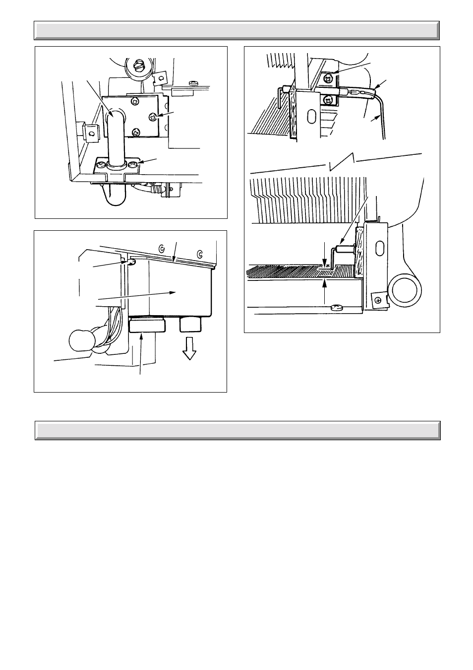
Diagram 12.9
Diagram 12.8
SECURING
SCREW (2)
SILICONE
SLEEVING
IGNITION
AND
SENSING LEAD
SPARK
ELECTRODE
SPARK GAP
3mm to 4mm
GASKET
SECURING
SCREW (3)
CONDENSE
DRAIN TRAP
CAP
WASTE
OUTLET
4060
4061
12 Servicing
Diagram 12.7
INJECTOR
MANIFOLD
SECURING
SCREW (3)
SECURING
SCREW (2)
4059
13 Fault Finding