Grizzly G0705 User Manual
Page 15
Model G0705 (Mfg. since 09/09)
-13-
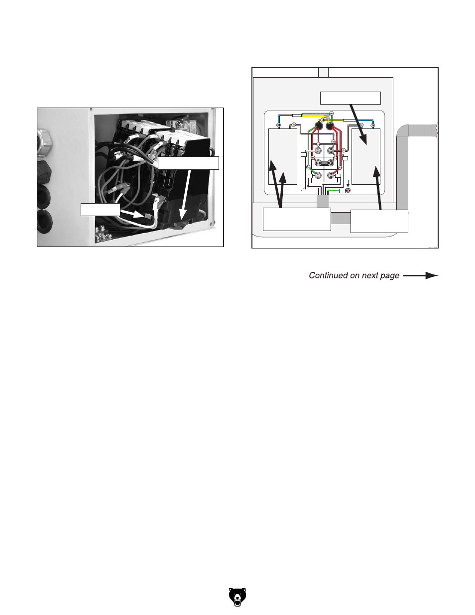
4. remove the screws that secure the brass
contactor mounting plate to the back of the
electrical box, then pull the contactors out
to access the gray tab shown in
figure 7.
pull outward on the gray tab to release each
contactor from the mounting plate.
5. install the two 110v contactors from the
Model g0705 110v Conversion Kit in place
of the contactors you removed in
step 4.
6. replace the wires you removed in step 3
to the corresponding terminals on the 110v
contactors. the wiring is the same for 110v
and 220v. refer to
section 8: Wiring
starting on
page 45 for detailed wiring dia-
grams.
7. locate the indicator lamp shown in figures 4
&
5. disconnect the two wires from its termi-
nals, then remove the lamp.
8. install the 110v indicator lamp from the
Model g0705 110v Conversion Kit in place
of the lamp you removed in
step 7.
9. Connect the wires you removed in step 7 to
the corresponding terminals on the 110v indi-
cator lamp. the wiring is the same for 110v
and 220v.
figure 7.
Contactor release tab location.
gray tab
Neutral
Hot
Ground
110 VAC
5-20 Plug
(As Recommended)
Hot
Hot
Ground
6-15 Plug
(As Recommended)
G
Ground
PE
V2
V1
U2
U1
U2
V1
V2
Z1
W1
Z2
W2
U1
U2
V1
V2
Z1
W1
Z2
W2
U1
To Electrical Box
Start
Capacitor
150 MFD
250 VAC
Run
Capacitor
20 MFD
450 VAC
110V Terminal
Block Jumper
Position.
(Wire positions
are the same for
110V/220V)
To Electrical Box
Cord Rewired for 110V
Motor 220V
figure 8.
Jumper positions on terminal block.
terminal Block
220v Jumper
location
10. locate the terminal block located in the motor
junction box, shown in
figure 8.
Mounting plate
Jumpers Moved
for 110v