Sanding drum/ sleeve installation, Sanding – Grizzly Oscilatign Spindle GO739 User Manual
Page 19
Model g0739 (Mfg. since 2/12)
-17-
Sanding Drum/
Sleeve Installation
to ensure the workpiece is supported during sand-
ing operations, use the table insert that matches
the corresponding drum and sleeve (see table
below). it is important to keep the gap between
the table insert and drum as small as possible to
reduce the risk of a pinch hazard.
Sanding
Sleeves
Sanding
Drums
Table
Inserts
Spindle
Washers
1
⁄
2
"
n/A
1
⁄
2
"
5
⁄
8
"
3
⁄
4
"
3
⁄
4
"
3
⁄
4
"
7
⁄
8
"
1"
1"
1"
7
⁄
8
"
1
1
⁄
2
"
1
1
⁄
2
"
1
1
⁄
2
"
1
3
⁄
4
"
2"
2"
2"
1
3
⁄
4
"
3"
3"
3"
1
3
⁄
4
"
To install or replace a sanding drum/sleeve:
1. disConnECt sAndEr FroM poWEr.
2. While holding the sanding drum and sleeve,
use the arbor wrench to loosen and remove
the spindle hex nut.
3. remove the spindle washer, sanding sleeve,
sanding drum, table insert and base washer
(see
figure 13).
4. Clean the table opening for the table insert
and any other spindle areas as necessary.
there should be no sawdust on the ledge of
the table opening where the table insert is
placed or the table insert will not sit flush with
the table.
5. Use the table on this page to select the
required size of components for the sanding
drum/sleeve size you have chosen.
6. insert the base washer, then install the
desired sanding drum on the spindle shaft,
followed by the corresponding sanding sleeve
on the drum, as shown in
figure 13.
7. secure the sanding drum with the appropri-
ate spindle washer and the spindle hex nut.
tighten until the rubber sanding drum places
slight pressure on the sanding sleeve.
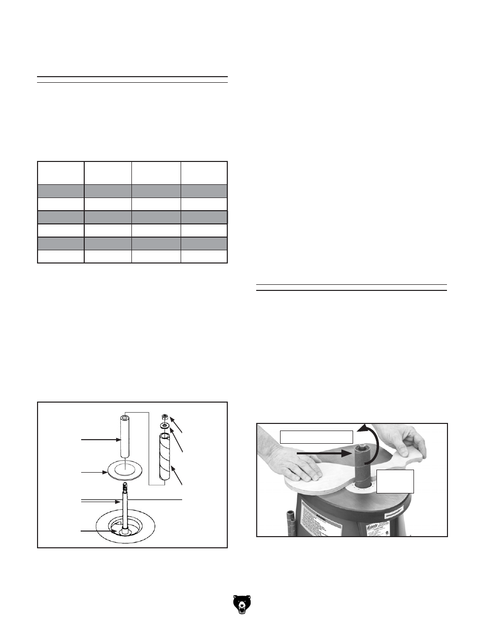
figure 13. removal/installation order of sanding
drum components and table inserts.
sanding
drum
table
insert
spindle
spindle
hex nut
spindle
Washer
sanding
sleeve
Base
Washer
Sanding
To sand a workpiece:
1. turn the spindle sander ON and allow it to
reach full speed.
2. Using both hands to maintain control of the
workpiece, guide the workpiece against the
rotation of the spindle, as shown in
figure
14. do not force the workpiece against the
sanding sleeve. Allow the machine to do the
work.
figure 14. sanding workpiece.
spindle
rotation
sanding direction