GTO Wireless Exit Sensors GTO User Manual
Page 5
W i r e l e s s E x i t S e n s o r
5
G
TO WIRELESS EXIT W
AND
TRANSMITTER
CODE
MED
TRANSMIT
A
CTIVE
MIN
MAX
SENSITIVITY
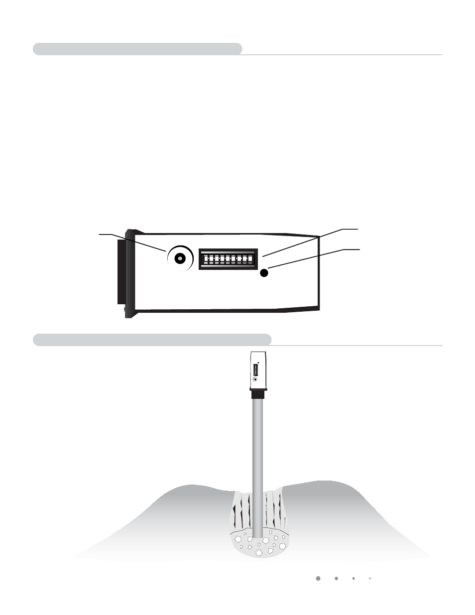
NOTE: The module should extend out
at least 12” above ground.
• Install and connect the RB709U-NB receiver to your gate operator as shown in the instructions supplied with
that receiver. You can skip this step if you have a GTO GEN3 control board on your gate operator.
• If using the RB709U-NB receiver, it is recommended that you disconnect the original antenna receiver that
came with your gate opener.
• Remove the outer cover from the Electronics/Transmitter Module.
• Set the transmitter Dip Switches. If you have GTO hand held transmitters for your gate, set the Dip Switches in
the Transmitter/Module to the same settings as the Dip Switches in your transmitter. If you do not have GTO
transmitters, set the Dip Switches to any desired setting. We do not recommend using the factory code
setting as shipped.
• Set the sensitivity control to mid scale (medium sensitivity).
• DO NOT install the batteries at this time!
GTO WIRELESS EXIT WAND
TRANSMITTER
CODE
MED
TRANSMIT
ACTIVE
MIN
MAX
SENSITIVITY
Sensitivity
Potentiometer
Dip Switches
Transmit Indicator
• Secure the Electronics/Transmitter Module on
the supplied PVC pipe by burying the bottom third
of the pipe in the soil and tamping the ground
around the pipe. DO NOT cover the electronics
module with a metal cover as this will cause
signal interference.
• This completes the hardware installation.
Electronics/Transmitter Module Setup
Planting the Electronics/Transmitter Module