2 installation, 1 locating the cylinder, 2 boiler heating circuit piping – Glowworm Lighting 250 I User Manual
Page 12: 3 motorised 2 port valve, 4 domestic hot water pipework, 5 thermostatic mixing valve, Diagram
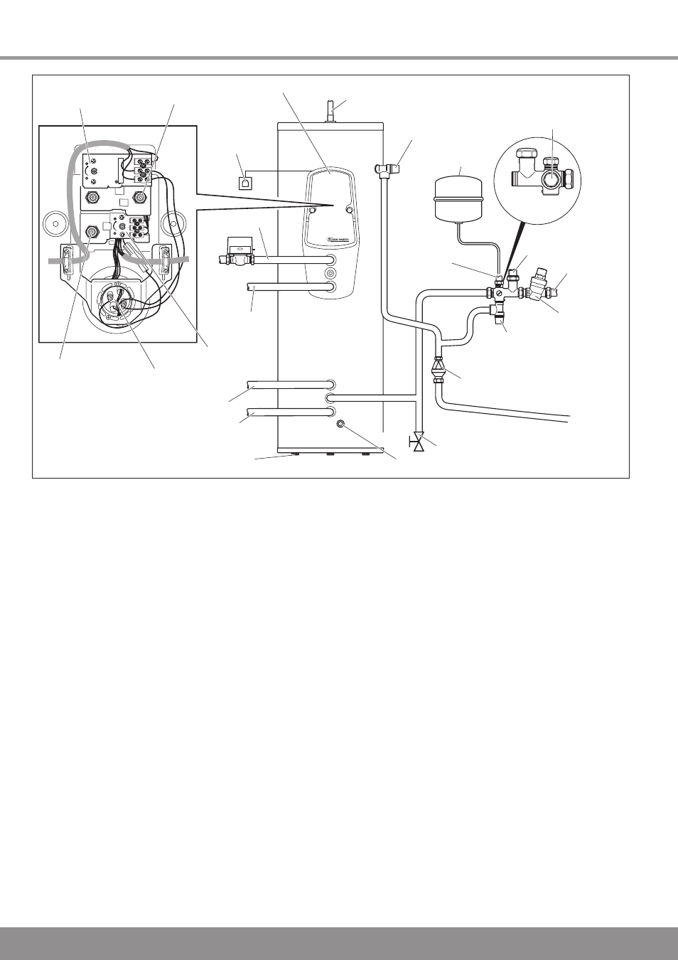
2 Installation
Legionella loop
return connection
Cylinder
thermostat
Cylinder thermostat
thermal cut out
Immersion heater
thermostat
Immersion heater
thermal cut out
Immersion
heater
Domestic hot water
outlet connection
Temperature and
Pressure relief valve
Expansion vessel
connection
Pressure controlled
cold water outlet
Cold water
supply
Return
(solar circuit)
Adjustable feet
Flow (solar circuit)
Return
(boiler)
Flow (boiler)
Solar pump thermal
cut out
Immersion
heater
switch
Pressure
limiting
valve
Expansion
relief
valve
Tundish
Cylinder drain valve
Temperature sensor immersion sleeve
Expansion
vessel
REAR VIEW
30°
40
°
50
°
65°
30°
40
°
50
°
65°
L
N
1
2
3
4
74
Diagram .
2.1 Locating the cylinder
Locate the solar cylinder at an appropriate place in the
building, while observing the following:
The discharge pipe from the tundish must be installed at a
minimum slope of :00 and end at a safe and visible point,
refer to section .9.
The installation surface must be level and able to bear the
weight of the full cylinder, refer to table ..
The installation site may not be prone to frost. A frost
protection thermostat must be installed if necessary.
There must be sufficient space to install, check and
repressurise the expansion vessel.
Floor unevenness should not be greater than the
compensation offered by the adjustable feet of the solar
cylinder.
2.2 Boiler heating circuit piping
Copper pipes with a minimum diameter of mm should be
used for the pipes in the reheating circuit between the boiler
and the solar cylinder.
Larger pipe diameters may be necessary for relatively large
distances between the boiler and the cylinder.
2.3 Motorised 2 port valve
To prevent the Flurocyl cylinder from overheating the port
motorised valve supplied must be fitted to the primary flow to
the indirect coil.
2.4 Domestic hot water pipework
Connect the hot water outlet to the mm hot water
connection of the solar cylinder.
Lay a further 22mm pipe to the first T-piece.
A pipe of 15mm diameter should then be sufficient.
If the pipe is very long or several outlets are supplied,
continue with another mm pipe.
2.5 Thermostatic mixing valve
A hot water thermostatic mixing valve ensures the hot water
from the cylinder is mixed with cold water to a desired
maximum temperature between 30°C and 60°C.
Set the thermostatic mixing valve to the desired maximum
temperature during the solar system commissioning.
IMPORTANT: Risk of scalding, Set the thermostat mixer to
60°C or below and check the temperature at a hot water tap
to ensure effective protection against scalding.