Notice, Installation, Utility closet dimensions – Friedrich 24,000 BTU/h User Manual
Page 7: Top view
5
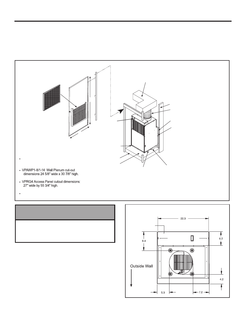
Installation
Utility Closet Dimensions
electrical
entrance
control box
Figure 4
Top View
Recommended utility closet dimensions and a typical indoor installation are illustrated in Figure 3. Three inches minimum clearance
on three sides of the unit must be allowed for return airflow, installation access and service access. See Figures 3 & 4 for clearances
and reference dimensions.
NOTICE
Drain pan must be installed in closet prior to chassis
insertion into plenum. See Page 10 for drain pan insta-
llation details. Failure to do so can result in property
damage.
Figure 3
Typical Utility Closet
Chassis Shown in Closet, on Optional Platform
Exterior Wall
Flexible Ductwork
Rigid Ductwork
VPAWP1-8/1-14Wall Plenum
Plenum
VPDP1 drain pan beneath
unit is required on all
VEA/VHA24 units. Drain
pan must be installed prior
to chassis installation
Chassis is
shipped with
vibration
isolators
installed
3" Clearance on all
three sides minimum for
service and installation
Optional Platform
Field-supplied
Filter (25" x 20")
58"
29"
Recommended field
installed drain pan
VPRG4 Access Panel &
Return Air Filter Grille
Power
Disconnect
Vert-I-Pak Chassis 2-ton dimensions:
23 1/8" wide x 23 1/8" deep x 47 1/4" high.
See Figure 16, page 14 for proper chasis
installation.
- 7,200 BTU Packaged Terminal Air Conditioner Warranty 920-087-09 (12/10) ZoneAire Series 42 Inch Packaged Terminal Air Conditioner Warranty A-SERIES 9 HEAT PUMPS 7,200 BTU Packaged Terminal Air Conditioner Product Profile 7,200 BTU Packaged Terminal Air Conditioner Installation and Operation Manual ZoneAire Series 42 Inch Packaged Terminal Air Conditioner Warranty Guide