Pin assignment of internal ports, Front panel, Serial ata – FUJITSU RELIABILITY D1859 User Manual
Page 16
Pin assignment of internal ports
10
D1859 (Econel 50)
Pin assignment of internal ports
The pin assignment of some internal connections is shown in English in the following.
i
Some of the following connectors may be optional!
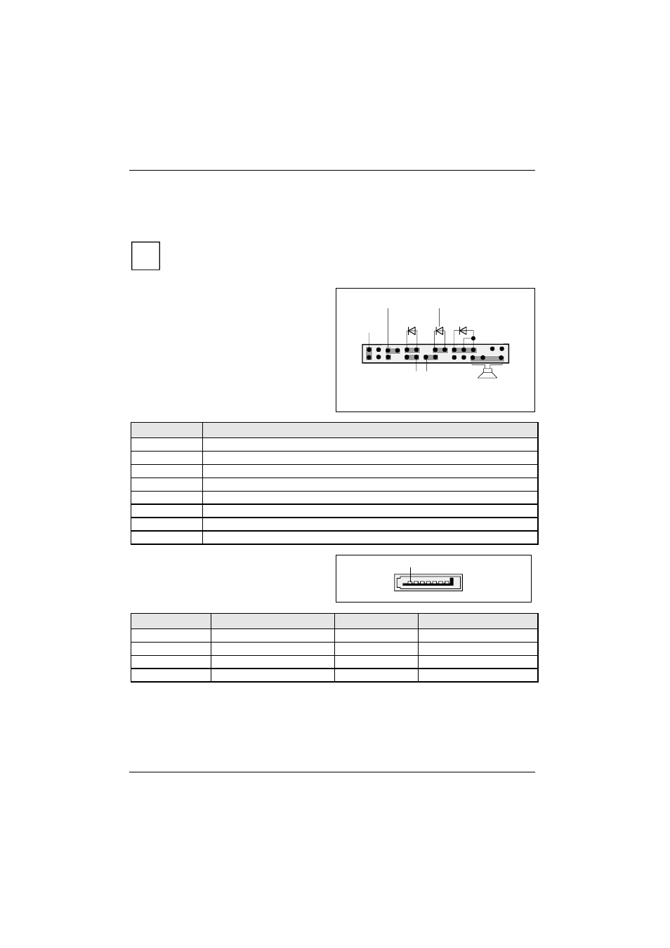
Front panel
Watch the poling of the LEDs. The positive pole
of the connection cables is often indicated with a
coloured wire.
1) Both jumper positions possible
2) 2pin or 3pin connector possible
1
2
HD-LED
Power On/Off
Recovery Password
1)
Reset
Power On
LED 2)
Message LED
Speaker
Connection
Note
Reset
Connector for reset switch
Power On/Off
Connection for ATX On/Off switch
HD LED
Indicates HDD (hard disk) activity
Message LED
Indicates system management error
Power On LED
Indicates the system state APM or ACPI
Recovery
see "Fehler! Verweisquelle konnte nicht gefunden werden." chapter
Password
see "Fehler! Verweisquelle konnte nicht gefunden werden." chapter
Speaker
0,5 W at 8 Ohm
Serial ATA
1
Pin
Signal
Pin
Signal
1
GND
2
Transmit data positive
3
Transmit data negative
4
GND
5
Receive data negative
6
Receive data positive
7
GND
8
Key