Hardware connections, Hardware connection tips / hints – FieldServer A Sierra Monitor Company X30 User Manual
Page 4
FS-8700-122 Profibus DP Master Manual
Page 4 of 13
FieldServer Technologies 1991 Tarob Court Milpitas, California 95035 USA Web: www.fieldserver.com
Tel: (408) 262 2299 Fax: (408) 262 2269 Toll Free: (888) 509 1970 email: [email protected]
HARDWARE CONNECTIONS
3
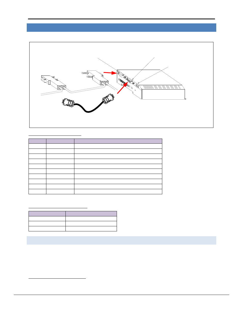
The FieldServer is connected to the Profibus network and NetTool as shown in the connection drawing below.
Profibus DB9 connector
NetTool RS-232 connector
Profibus Status LEDs
HMS Anybus NetTool RS-232 Serial Cable
Profibus DB9 Connector Pinouts
Pin
Name
Description
Housing Shield
Connected to PE
1
Not connected -
2
Not connected -
3
B-Line
Positive RxD/TxD according to RS-485 specification
4
RTS
1
Request to Send
5
GND BUS
2
Isolated GND from RS-485 side
6
+5V BUS
Isolated +5V from RS-485 side
7
Not connected -
8
A-Line
Negative RxD/TxD according to RS-485 specification
9
Not connected -
Only A-line, B-line and Shield are used for most applications.
Profibus NetTool connector Pinouts
PC Side DB9 Female FieldServer Side DB9 Female
2
3
3
2
5
5
3.1
Hardware Connection Tips / Hints
Use the recommended network cable and terminators as specified by the Profibus network organization and/or
the manufacturer of the network equipment.
1
Used in some equipment to determine the direction of transmission.
2
Used for bus termination. Some devices, e.g. optical transceivers (RS-485 to fiber optics) require an external power supply from these pins.