FUJITSU P42VHA30W User Manual
Page 5
5
English
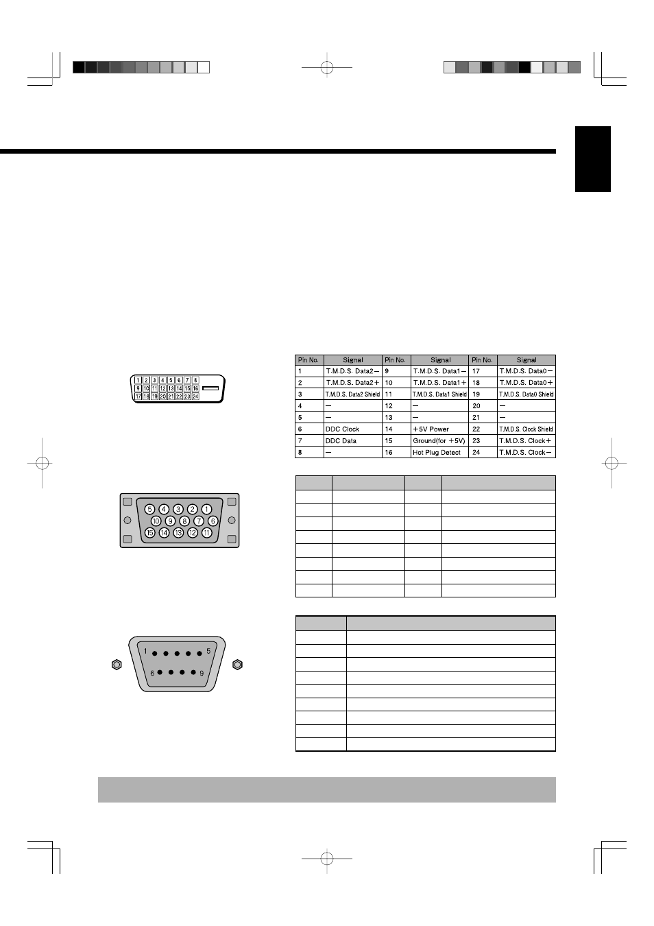
Description of Input Terminals
DVI-D terminal (RGB1 INPUT/DVI-D)
Pin No.
Input signal
Pin No.
Input signal
1
Red
9
—
2
Green
10
Ground
3
Blue
11
—
4
—
12
—
5
Ground
13
Horizontal synchronization
6
Ground
14
Vertical synchronization
7
Ground
15
—
8
Ground
Frame
Ground
RGB2 input terminal (RGB2 INPUT/mD-sub)
Pin No.
Signal
1
DCD (Data Carrier Detect)
2
RD (Received Data)
3
TD (Transmit Data)
4
DTR (Data Terminal ready)
5
GND (Ground)
6
DSR (Data Set Ready)
7
RTS (Request To send)
8
CTS (Clear To Send)
9
RI (Ring Indication)
RS-232C terminal (RS-232C)
9 Audio3 input terminal (AUDIO3 INPUT)
0 Audio2 input terminal (AUDIO2 INPUT)
A Audio1 input terminal (AUDIO1 INPUT)
Connect this terminal to the audio output terminal of your VCR, etc. (See the User’s manual (2/2) for the selection of audio input for
video input.)
B External speaker output terminal (EXT SP)
Connect this terminal to the optionally available speaker.
When connecting a cable, attach a ferrite core to the cable. (See P. E-2.)
*See the speaker instruction manual for more information.
C Power input terminal
Connect this terminal to the power cable supplied with the display.
When connecting a cable, attach a ferrite core to the cable. (See P. E-2.)
* Terminal layout may differ and functions may not be available with some models and some device options.
03.10.9, 8:32 PM
Page 5