Part names and functions (continued) – FUJITSU P42VHA30W User Manual
Page 4
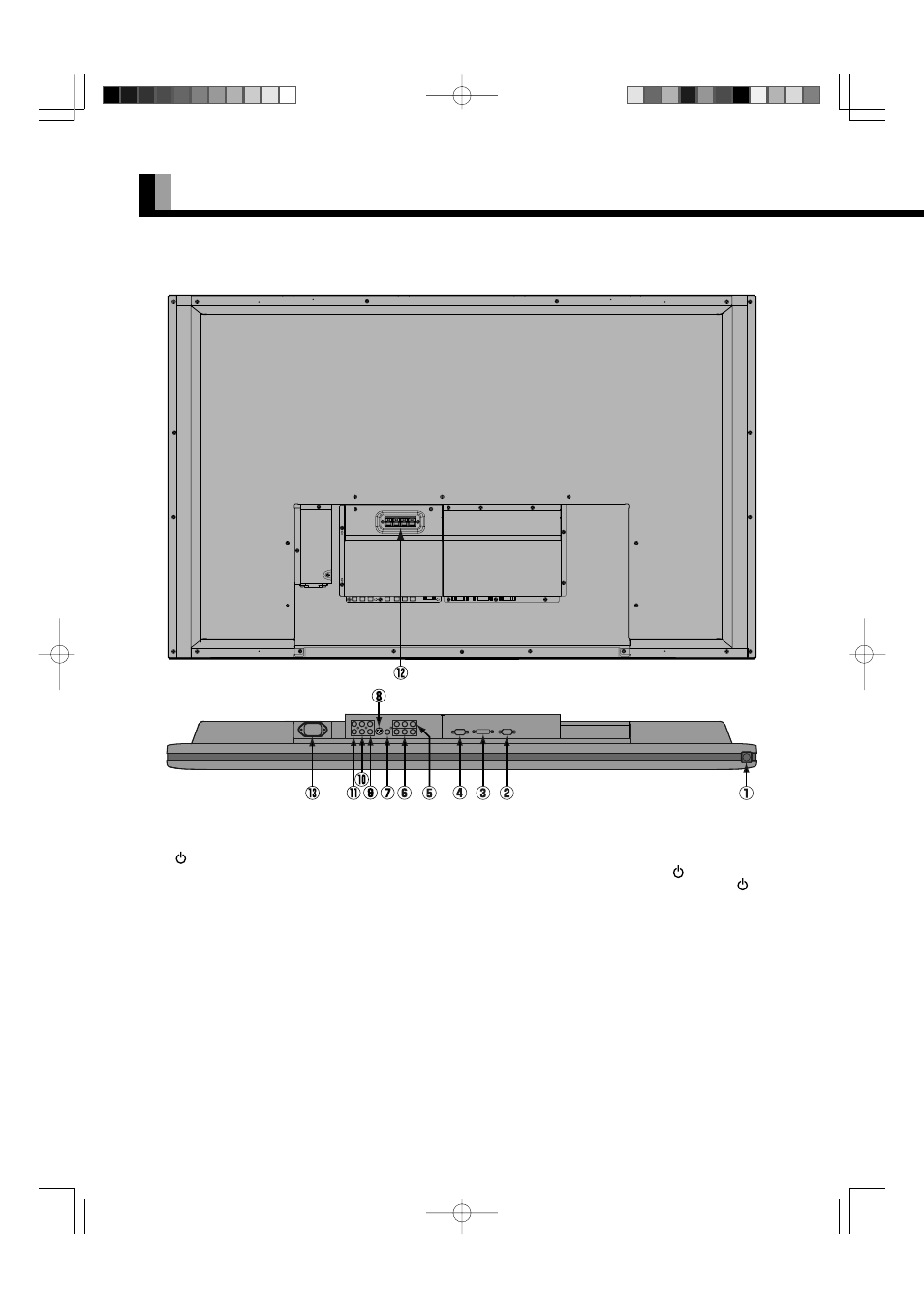
4
1
/I power switch
When pressed while in the “OFF” state, the power indicator lamp lights and the display is placed in the “ON
” state, and the power
can be turned “ON” or “OFF” by the remote control or on the control panel of the display. When pressed while in the “ON
” state,
the power indicator lamp goes out and the display is placed in the “OFF” state where power is still partly supplied.
2 RS-232C terminal (RS-232C)
This terminal is provided for you to control the display from the PC. Connect it to the RS-232C terminal on the PC.
When connecting a cable, attach a ferrite core to the cable. (See P. E-2.)
3 RGB1 input terminal (RGB1 INPUT/DVI-D)
Connect this terminal to the PC’s display (digital RGB) output terminal.
*The connection cable No.88741-8000 made by molex Inc. is recommanded.
4 RGB2 input terminal (RGB2 INPUT/mD-sub)
Connect this terminal to the PC’s display (analog RGB) output terminal or decoder (digital broadcast tuner, etc.) output terminal.
5 Component video input terminal (VIDEO3 INPUT)
6 Component video input terminal (VIDEO4 INPUT)
Connect this terminal to the component video output (color difference output) terminal of your HDTV unit or DVD player.
7 Video input terminal (VIDEO1 INPUT)
Connect this terminal to the video output terminal of your VCR.
8 S-Video input terminal (VIDEO2 INPUT)
Connect this terminal to the S-video output terminal of your VCR.
PART NAMES AND FUNCTIONS (Continued)
Back and bottom
03.10.9, 8:32 PM
Page 4