Field wiring diagrams, Connecting beverage lines – Follett VU300 User Manual
Page 8
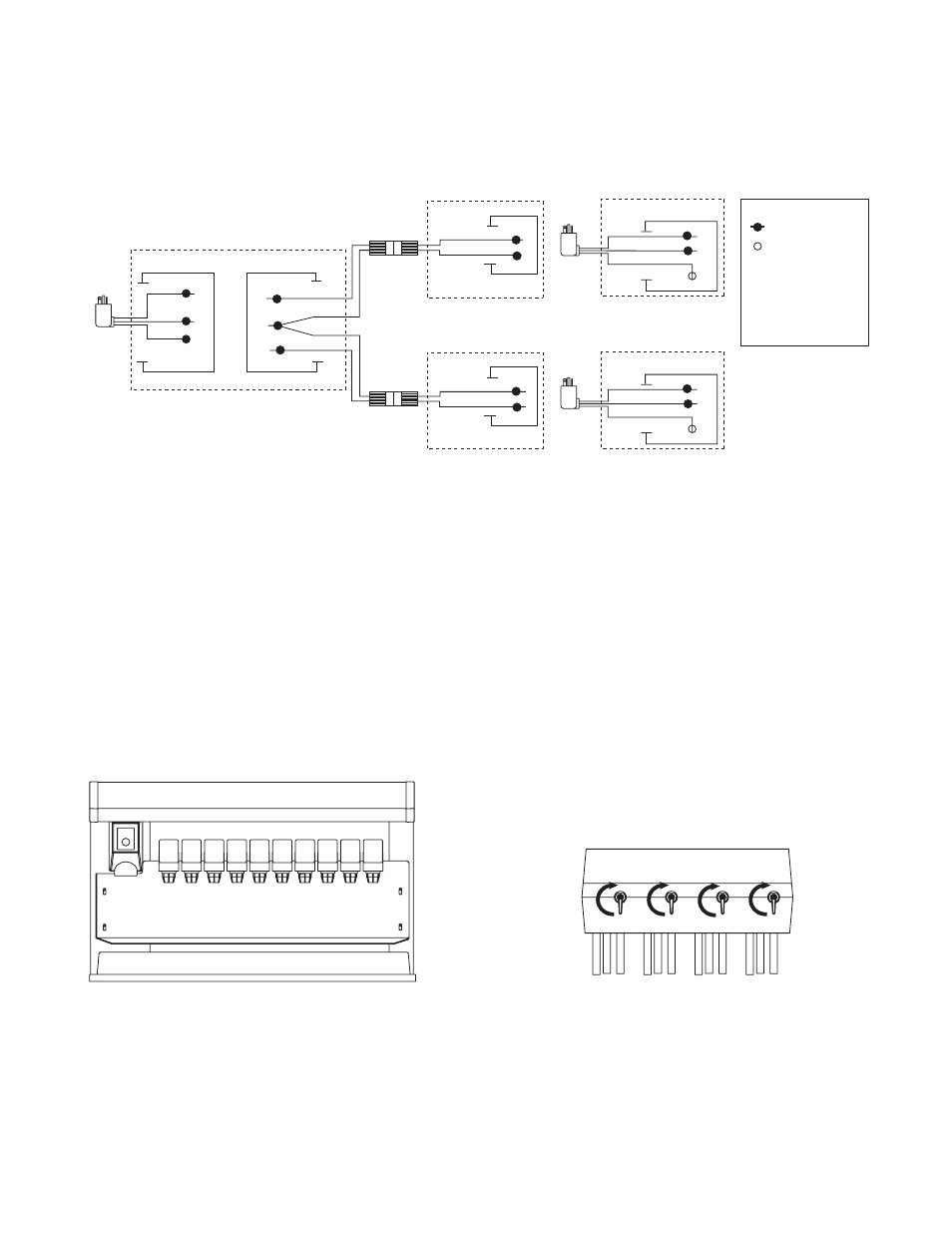
Field wiring diagrams
Note: Field wiring diagrams are intended to aid electricians or technicians in understanding how equipment
works. All field wiring must be installed in accordance with all local and NEC codes.
LEGEND
WIRENUT FIELD
CONNECTIONS
X
EQUIPMENT
GROUND
B
W
GRN
BL
Y
DISPENSER
If attaching optional Chewblet MC400A
auto-fill icemaker kit(s)
LEFT JUNCTION BOX
RIGHT JUNCTION BOX
BL
Y
RD
W
B
LOWER JUNCTION BOX
ICEMAKER #2
(OPTIONAL)
W
B
X
GND
GRN
B
W
LOWER JUNCTION BOX
ICEMAKER #1
(OPTIONAL)
UPPER JUNCTION BOX
BLACK
WHITE
GREEN
BLUE
YELLOW
RD
RED
ELECTRIC
POWER
SOURCE
X
GND
GRN
B
W
UPPER JUNCTION BOX
ELECTRIC
POWER
SOURCE
Electric
Power
Source
GND
GRN
B
W
9
Connecting beverage lines
1. Connect syrup and water lines. Non-carbonated water line will be labeled “water”. Syrup lines are numbered
and correspond to the valves as shown in drawing(s) below. Valve one is always next to ice tower.
2. The center 4 valves are pre-plumbed to both carbonated and non-carbonated water lines with the
QuickCARB™ beverage manifold. Valves can be individually changed from a carbonated to a non-carbonated
flavor with the flip of a lever (see below).
3. Clean and sanitize beverage lines according to cleaning instructions.
Valve position #1 is always next to ice
tower. Left-hand unit shown.
10
9
8
7
6
5
4
3
2
1
carbonated
non-carbonated
VU300B QuickCARB manifold
(see dispenser for model specific
QuickCARB configuration)
Rear View