Attention – Field Controls Heat Recovery Ventilator FC95HRV. User Manual
Page 20
20
Installation of the Dehumidistat or Dehumidistat Ventilation Control
Standard Series Controls may be installed onto a flush mounted
2" x 4" electrical switch box or it may be surface mounted onto a
wall.
Only 1 master control should be installed to a ventilation system
(the Face Plate on this illustration may not be exactly the same as
yours).
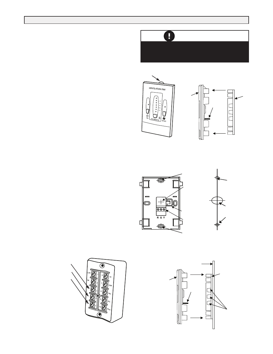
1. Remove the Operating Instructions Card from the top of the
Control (Figure A).
2. Separate the Face Plate from the Back Plate by firmly pulling
apart (Figure B). Be careful not to damage Face Plate Contact
Pins.
3. Place the Back Plate of the control in the desired location on
the wall and pencil mark the wall in the center of the Wire
Opening, Top Screw Hole and Bottom Screw Hole (Figure C).
4. Remove the Back Plate and drill a 3/8" opening in the wall to
allow for the Wire Opening and a 1/8" hole for the Wall
Anchors for the top and bottom screw holes (Figure D).
5. Pull 3/20 wire through the opening in the wall and the Wire
Opening of the Back Plate (Figure C).
6. Connect Red, Green and Yellow to the Wiring Terminals
located on the Back Plate (Figure C).
7. Secure a single wire to the Wire Retainer located on the Back
Plate (Figure C).
8. Attach the Back Plate to the wall using the 2 supplied screws
and anchors.
9. Attach the Face Plate to the Back Plate (Figure B).
Note: Be careful to correctly align the Face Plate to avoid
damaging the Face Plate Contact Pins.
10. Insert the Operating Instructions Card into the control (Figure
A).
11. Connect the 3/20 wire to the Terminal Block located on
ventilator (Figure E).
ATTENTION
Pay special attention not to damage the Contact
Pins when attaching and detaching the Face Plate.
(Figure B)
Operating
Instructions Card
Figure A -
Face Plate
Figure E
Terminal Block located
on ventilator
• Yellow to YELLOW #4
• Red to RED #3
• Green to GREEN #5
Use 3/20 wire
Red #3
Yellow #4
Green #5
Back
Plate
Figure B
Face Plate
Contact
Pins
Face
Plate
Separate the
Face Plate from
the Back Plate.
Side View
P
Figure C
Front View of Back Plate
Wire
Opening
Wiring
Terminals
Wire
Retainer
TOP
Top Screw
Hole
Bottom
Screw Hole
Drill a 1/8” hole
for the Top Screw
and Anchor
Figure D
Drill holes in wall
Drill a 3/8” hole
for the Wire
opening
Drill a 1/8” hole
for the Bottom
Screw and
Anchor
F
Correct Installation
of Back Plate
Wall Face
Dehumidistat Sensor
Openings to room
air allow accurate
sensor readings.
Figure F
Back
Plate
Face Plate
Contact
Pins
Face
Plate